Chapter 2: Installation and Wiring
2–2
SOLO Basic Temperature Controller User Manual
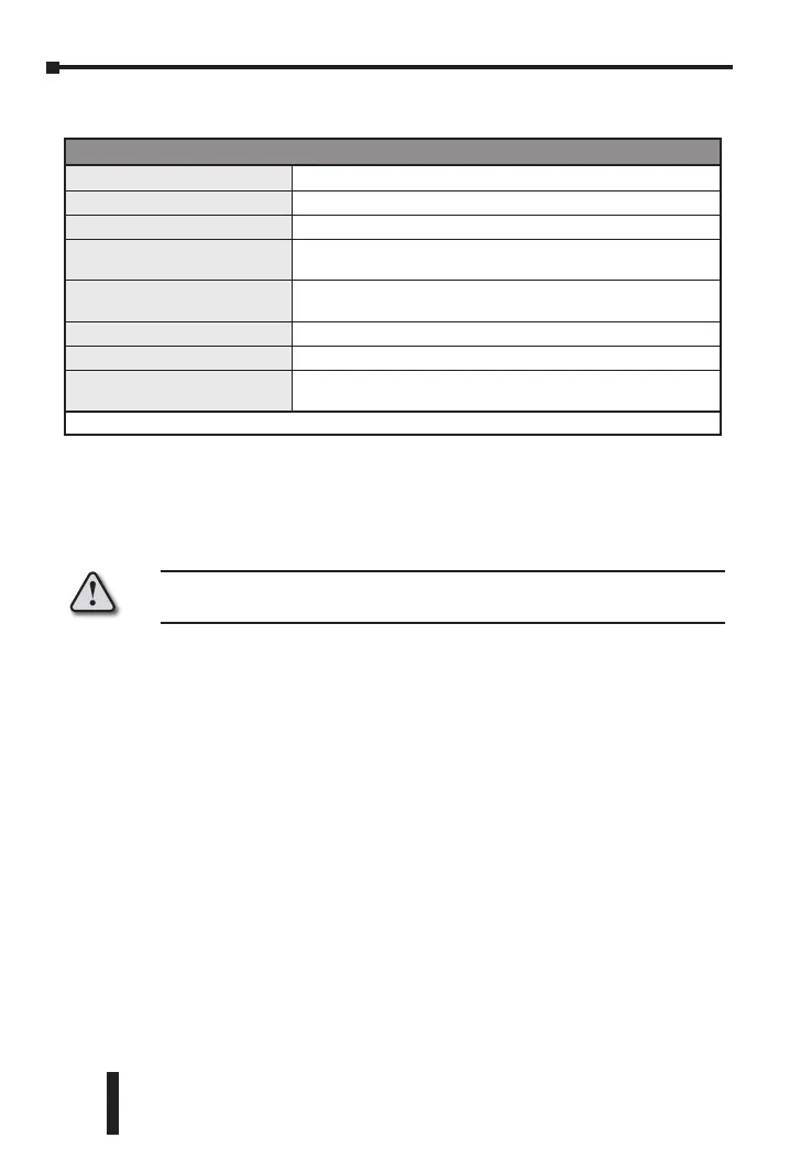
Ambient Conditions
Ambient Conditions
Ambient Temperature Range
32°F to 122°F (0°C to 50°C)
Storage Temperature Range
-4°F to 149°F (-20°C to 65°C)
Relative Humidity
35% to 80% (non-condensing)
Altitude
2000m or lower above sea level,
keep from corrosive gas, liquid and dust
Pollution Degree
Degree 2 - Normally, only non-conductive pollution occurs.
Temporary conductivity caused by condensation is to be expected.
Vibration Resistance
10 to 55 Hz, 10 m/s2 for 10 min, each in X, Y and Z directions
Shock Resistance
Max. 300 m/s2, 3 times in each 3 axes, 6 directions
IP Rating
IP66: Complete protection against dust and powerful water jets from
all directions. (*inside suitable enclosure)
* No corrosive gases
Installation Considerations
Improper installation of the controller will greatly reduce its life. Be sure to
observe the following precautions when selecting a mounting location:
Warning: Failure to observe these precautions may damage the controller
and void the warranty!
• Do not mount the controller near heat-radiating elements or in direct
sunlight.
• Do not install the controller in a place subjected to high temperature, high
humidity, excessive vibration, corrosive gases or liquids, or airborne dust or
metallic particles.
• Do not restrict the air flow to the vent opening on the controller housing
• This controller is an open-type unit and must be placed in an enclosure to
ensure proper operation and maintain the IP66 rating.
Mounting Instructions
SLB4848 Series
SOLO Basic temperature controllers should be mounted through a cutout in
an enclosure or panel by using the dimensions shown on page 2–4. The
directions for mounting the controller through a cutout are:
1. Insert the temperature controller through the panel cutout.
2. Slide the M3X0.5 nut into the opening in the top of the mounting bracket and
insert the M3X0.5 X 30mm mounting screw in the mounting bracket.