SE3-USER-M
15
1st Edition, Dec. 2023
SE3 Series Industrial Unmanaged Ethernet Switches User Manual
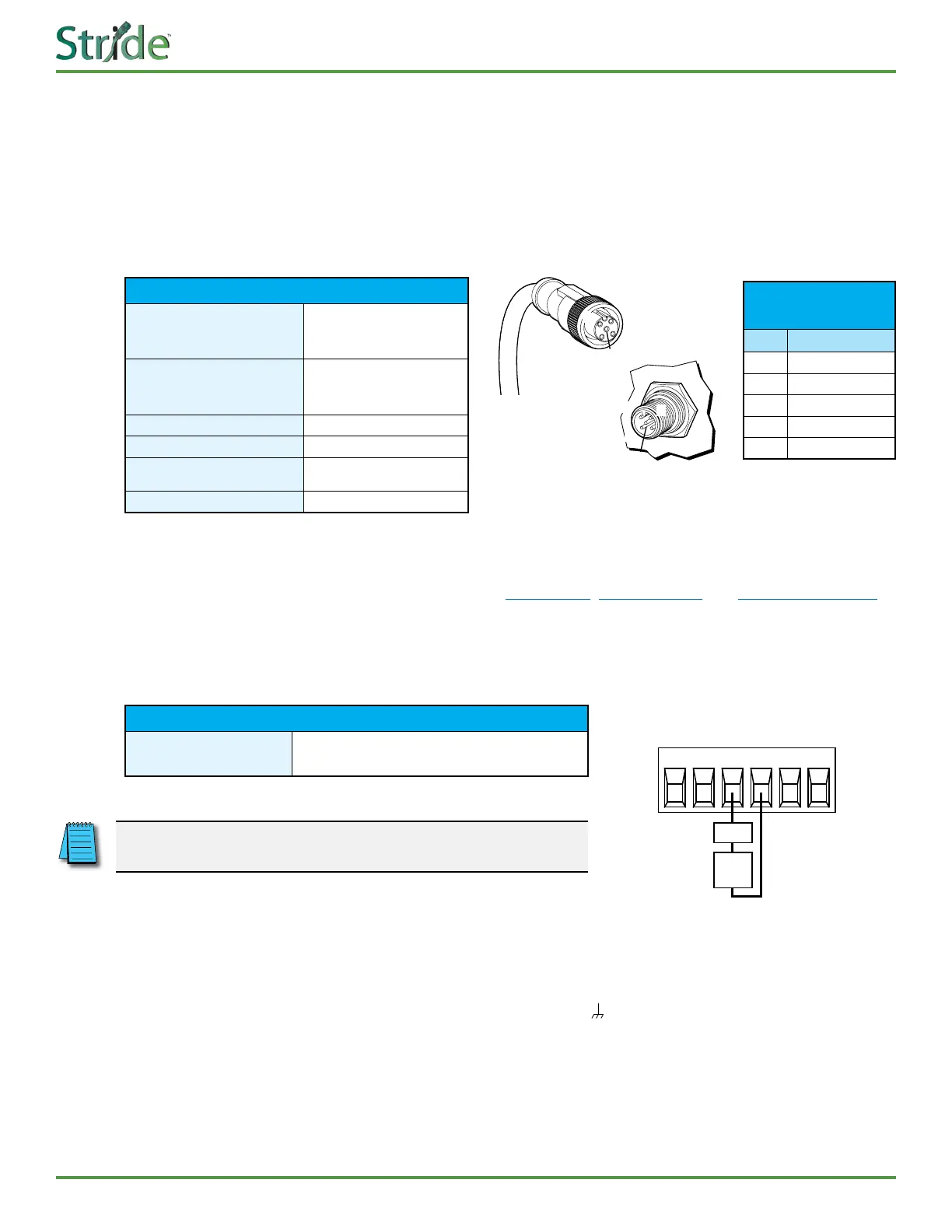
M12 Power Inputs
e switch can be powered from the same source that is used to power your other devices. A DC voltage in
the range of 12–48 VDC needs to be applied through an M12 connector as shown in the chart below. We
recommended grounding the switch to the panel or chassis ground using an M3 or M4 ground screw and
grounding wire, attached to either the top or bottom wall mounting hole. To reduce down time resulting
from power loss, the switch can be powered redundantly with a second power supply as shown in the chart
below. A recommended DC power supply is AutomationDirect.com part number PSL-24-030.
M12 Power Details
Power Connection
Dual DC power inputs
through M12 5-pin A-coded
male connector
Input Voltage
Class 2 power supply:
12–48 VDC redundant
power inputs
Reverse Power Protection
Yes
Wire Size
24–18 AWG
System Power
Consumption
0.5 W
Relay Contact
No
Alarm Wiring
All SE3 series switches, with the exception of Models SE3-SW5U, SE3-SW5U-T and SE3-SW5U-N67-T,
have a Power Fault alarm contact. Terminals for the alarm are located between the power inputs on the
removable terminal block, as shown below. e alarm is a normally open contact that is held closed by the
presence of power on both power inputs. On loss of one or both power sources, the alarm contact will open.
Power Fault Alarm Details
Relay Contact
24VDC, 1A resistive, open on fault (not present on
SE3-SW5U, SE3-SW5U-T, SE3-SW5U-N67-T)
NOTE: If only one power supply is used, jumper V1+ to V2+ and
V1- to V2- to eliminate power fault alarm.
Grounding
Grounding and wire routing help limit the eects of noise due to electromagnetic interference (EMI).
Run a ground connection from the ground screw on the switch ( ) to the grounding surface prior to
connecting devices.
On Model SE3-SW5U-N67-T, which does not have a designated ground screw, we recommend grounding
the switch to the panel or chassis ground using an M3 or M4 ground screw and grounding wire, attached
to either the top or bottom wall mounting hole.
Power Port
Pin Denitions
Pin Description
1 Power Input 1 +
2 Power Input 2 +
3 Power Input 2 -
4 Power Input 1 -
5 Ground
1
2
4
3
5
1
2
3
4
5
V1+ V2-V1- V2+
PWR1 PWR2FAULT*
LOAD
EXT
PWR
*Fault Contact opens when in a faulted state
(Not present on some models)