SE3-USER-M
16
1st Edition, Dec. 2023
SE3 Series Industrial Unmanaged Ethernet Switches User Manual
Communications Wiring
e industrial Ethernet switches provide connections to standard Ethernet devices such as PLCs, Ethernet
I/O, industrial computers and much more. RJ45 or M12 (for IP67 locations) Ethernet ports or ber/SFP
option ports are available depending on model.
Please see www.automationdirect.com for a wide range of cabling options.
RJ-45 Ethernet Connections
Use data-quality (not voice-quality) twisted pair cable rated category 5e (or better) with standard RJ45 or
M12 (D-coded, male, 5-pin) connectors. Straight-through or crossover Ethernet cable can be used for all
devices to which the switch is connected because all the ports are capable of auto-MDI/MDIX crossover
detection. e maximum cable length for 10/100/1000BaseT is 100m [328ft].
e RJ45 Ethernet port connector bodies on these products are metallic and connected to the Chassis
GND terminal. erefore, shielded cables may be used to provide further protection. To prevent ground
loops, the cable shield should be tied to the metal connector body at one end of the cable only. Electrical
isolation is also provided on the Ethernet ports for increased reliability.
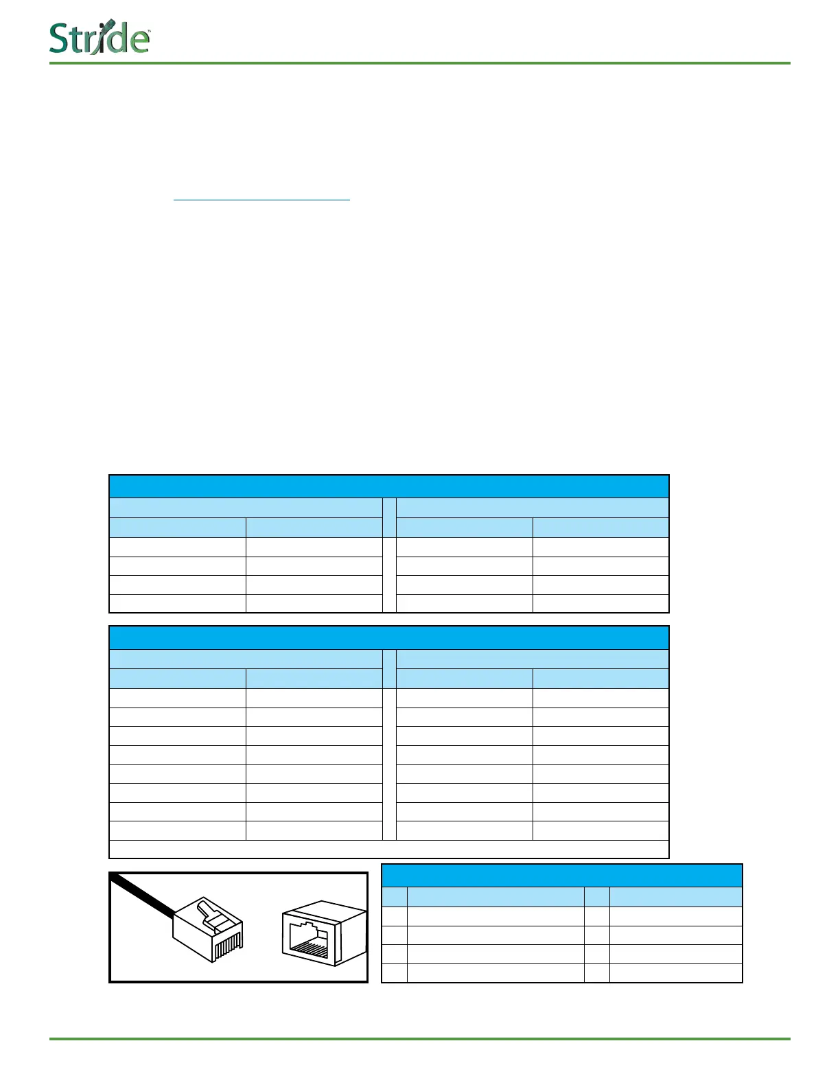
e RJ-45 ports are auto-sensing for 10Base-T, 100Base-TX or 1000Base-T devices connections. See the
gures as below for straight-through and crossover cabling schematics.
10/100Base-T(X) RJ-45 Pin Assignments
Crossover Cable Straight-through Cable
Pin Number / Signal Pin Number / Signal Pin Number / Signal Pin Number / Signal
1 / RX+ 3 / TX+ 1 / RX+ 1 / TX+
2 / RX- 6 / TX- 2 / RX- 2 / TX-
3 / TX+ 1 / RX+ 3 / TX+ 3 / RX+
6 / TX- 2 / RX- 6 / TX- 6 / RX-
1000Base-T RJ-45 Pin Assignments
Crossover Cable Straight-through Cable
Pin Number / Signal Pin Number / Signal Pin Number / Signal Pin Number / Signal
1 / TP0+ 3 / TP1+ 1 / TP0+ 1 / TP1+
2 / TP0- 6 / TP1- 2 / TP0- 2 / TP1-
3 / TP1+ 1 / TP0+ 3 / TP1+ 3 / TP0+
4 / TP2+ 7 / TP3+ 4 / TP2+ 4 / TP3+
5 / TP2- 8 / TP3- 5 / TP2- 5 / TP3-
6 / TP1- 2 / TP0- 6 / TP1- 6 / TP0-
7 / TP3+ 4 / TP2+ 7 / TP3+ 7 / TP2+
8 / TP3- 5 / TP2- 8 / TP3- 8 / TP2-
Note: “+” and “-” signs represent the polarity of the wires that make up each wire pair.
8
1
8
PoE Switch Ethernet Port Pin Denitions
Pin Pin
1 V - 5 TRD2 -
2 V + 6 V -
3 V - 7 TRD3 +
4 TRD2 + (transmit / receive data) 8 TRD3 -
 Loading...