H-86
TZN/TZ Series
Communication output
Calculation range of Block Check Character
Start
Code
Header
Code
END
Code
BCC
Code
Address
Code
Text
STX 10
1
10
0
R/W X/D ETX FSC
Supply system power
※
A → Over min. 4sec, B → Within max. 300ms, C → Over min. 20ms
A B CTZ/TZN
S
T
X
A
D
R
C
M
D
T
X
T
E
T
X
B
C
C
S
T
X
A
D
R
C
M
D
T
X
T
E
T
X
B
C
C
A
C
K
S
T
X
A
D
R
C
M
D
T
X
T
E
T
X
B
C
C
Master
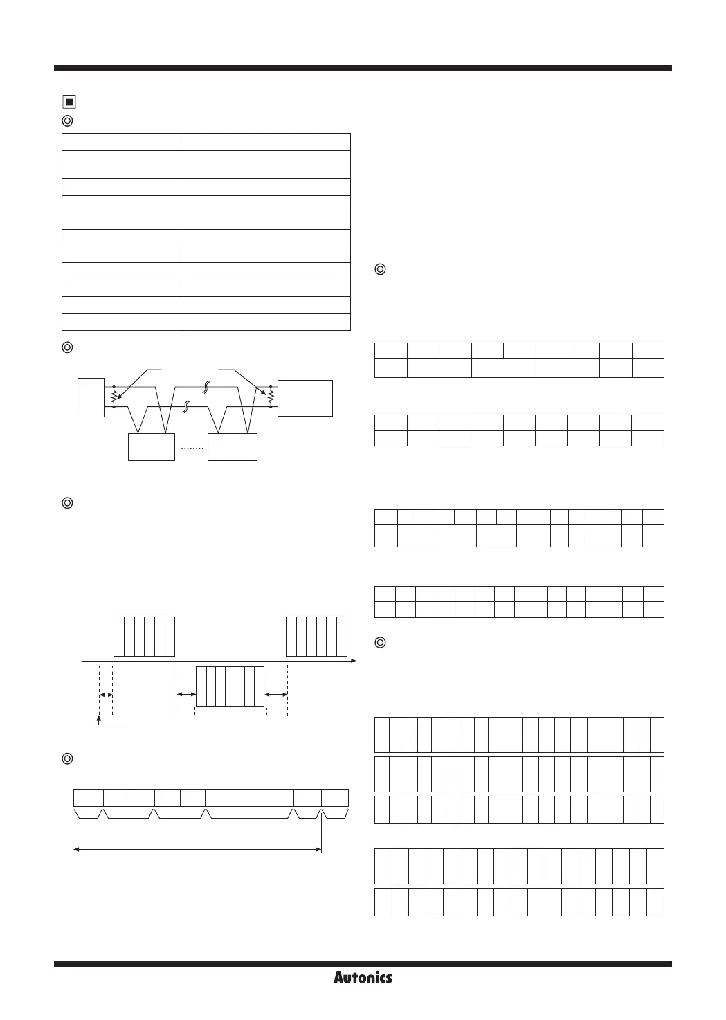
Interface
Standard EIA RS485
Number of connections
Max. 31units. It is available to
set address 01 to 99.
Communication method 2 wire half duplex
Synchronous method Asynchronous type
Communication distance Within 1.2km
Communication speed 2400, 4800, 9600(available to set)
Start bit 1bit(Fixed)
Stop bit 1bit(Fixed)
Parity bit None
Data bit 8bit(Fixed)
Protocol BCC
Upper
Terminating
resistance
N
1 (N-1)
TZ/TZN TZ/TZN
TZ/TZN
(A+) (A+)
(A+)
(B-) (B-)
(B-)
RX(-)
TX(+)
System ordering
※
Use a proper twist pair for communication.
Communication control ordering
1. The communication control ordering of TZ/TZN
Series
is
exclusive protocol.
2. After 4sec. being supplied the power into master system,
then able to start communicating.
3. Initial communication will be started by master system.
When Command signal comes out from master system
then TZ/TZN
Series
will respond.
Communication Command and Block
Format of Command and Response
①
Start code
It indicates the first of Block STX → [02H],
in case of response, ACK will be added.
②
Address code
This code is master system can discern TZ/TZN
Series
and able to set within range of 01 to 99.(BCD ASCII)
③
Header code:
It indicates command as 2 alphabets as below.
RX(Read request) → R[52H], X[58H]
RD(Read response) → R[52H], D[44H]
WX(Write request) → W[57H], R[58H]
WD(Write response) → W[57H], D[44H]
④
Text: It indicates the detail contents of Command/
Response. (see command)
⑤
END code: It indicates the end of Block. ETX → [03H]
⑥
BCC: It indicates XOR operating value from the first to
ETX of the protocol as abbreviation of TZ/TZN.
Communication Command
● Read [RX] of measurement/setting value :
Address 01, Command RX
1.Command (Master)
①
Command
STX 0 1 R X P 0 ETX FSC
Start Address
Command
head
P:Process value
S:Setting value
End BCC
②
Application: Address(01), Header code(RX),
Process value(P)
STX 0 1 R X P 0 ETX FSC
02 30 31 52 58 50 30 03 BCC
● Write [WX] of setting value: Address 01, Command WX
1.Command(Master)
①
Command
STX 0 1 W X S 0 Symbol 10
3
10
2
10
1
10
0
ETX FSC
Start Address
Command
head
S:Setting
value
Space/- 10
3
10
2
10
1
10
0
End BCC
②
Application: In case of writing Address(01), Heading
Coad(WX), Setting value(S) +123.
STX 0 1 W X S 0 Symbol 10
3
10
2
10
1
10
0
ETX FSC
02 30 31 57 58 53 30 20 30 31 32 33 03 BCC
Response
● Read of process/Setting value
1. In case of receiving normal process value :
The data is transmitted adding ACK[60H].
(In case process value is +123.4)
A
C
K
S
T
X
0 1 R D P 0 Symbol 10
3
10
2
10
1
10
0
Decimal
point
E
T
X
F
S
C
N
U
L
L
A
C
K
S
T
X
0 1 R D P 0 Space 1 2 3 4 1
E
T
X
B
C
C
N
U
L
L
06 02 30 31 52 44 50 30 20 31 32 33 34 31 03
B
C
C
00
2. In case process value is -100
A
C
K
S
T
X
0 1 R D P 0
-
0 1 0 0 0
E
T
X
B
C
C
N
U
L
L
06 02 30 31 52 44 50 30 2D 30 31 30 30 30 03
B
C
C
00
※
It is responded with 1 byte sized NULL(00H) at the end
of response frame (next BCC 16).
 Loading...