Page - 21
PoolSync
TM
Device Connection
1.
Turn off power to the ChlorSync
®
unit.
2.
Remove the power center cover and the grommet in one of the available openings on the bottom of the
box.
3.
Insert the strain relief fitting provided with the PoolSync
TM
device. Route the antenna wire thorough the
strain relief and into the power center.
4.
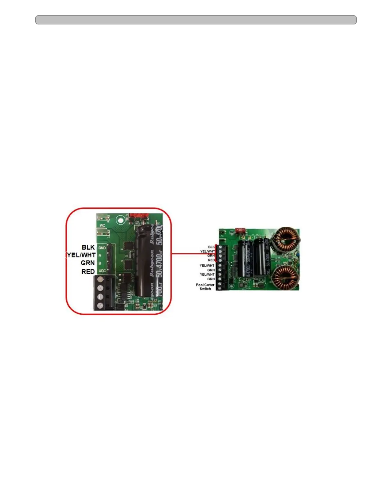
There is one (1) - four position connector and two (2) - two position connectors located on the front of
the board for wiring compatible devices. Remove the four position connector by pulling up on the black
plastic body.
5.
Connect the stripped end of the wires to the corresponding terminal on the PCB connector as shown in
the diagram below.
6.
When connection is made, verify the wires are firmly held in place by gently pulling on the wire.
7.
Replace the connector onto the PCB header pins. Be sure to align correctly.
8.
Tighten the strain relief, replace the power center cover and restore power to the unit.
9.
Before mounting the PoolSync
TM
to the wall, verify WiFi reception.
l Black wire from PoolSync
TM
to BLK (or GND)
l Yellow or White wire from PoolSync
TM
to YEL (or A)
l Green wire from PoolSync
TM
to GRN (or B)
l Red wire from PoolSync
TM
to RED (VDC or 10v)
PoolSync
TM
Wiring Location
Figure 11