Page - 22
Plumbing Installation
WARNING - Failure to heed the following may result in permanent injury or death.
l RISK OF ELECTRICAL SHOCK - Disconnect all AC power when installing or servicing this system.
Follow all state, local, and National Electrical Code(s) (provincial and Canadian Electrical Code(s) if
applicable) unless local guidelines supersede. Use copper conductors only.
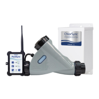
This section outlines basic installation of the ChlorSync
®
to the pool plumbing system. Before
attempting the installation, verify the following items have been included with the system.
Parts Included
l One(1) ChlorSync
®
cell
l Two (2) cell unions with two (2) o-rings
l Installation and User’s Guide (this manual)
Required Tools for Installation (Not included)
l Phillips and small tipped 1/8" flat head screwdriver
l Pliers or wire strippers
l Hacksaw or pipe cutter
l NSF approved all purpose PVC / CPVC / ABS cleaner primer and cement
Installation Recommendations
Figure 12 shows a typical ChlorSync
®
system installation. Please note this diagram is not drawn
to scale.
WARNING - Failure to heed the following may result in permanent injury or death.
l Do not operate the ChlorSync
®
unit if the cell housing is damaged or improperly installed.
The ChlorSync
®
should be plumbed into the dedicated pool return line (including pool/spa
combination installations) after the filter and heater, if applicable.
The ChlorSync
®
unit requires a minimum flow rate of 20 gpm (76 L/min). For accurate flow
detection, provide at least 12”-18” (30 cm - 46 cm) of straight pipe in front of the cell inlet.
Pipe unions: Maximum pressure 50 psi at 70°F (21°C).
To Install the ChlorSync
®
Cell:
1.
Measure and cut out a section of plumbing to fit the cell.
2.
Attach the PVC unions to the plumbing pipe, using PVC glue. Allow the glue to dry before proceeding
to the next step.
3.
Orient the cell in a horizontal position. Be sure there is sufficient access to the cell control panel for
programming and maintenance.
4.
Install the cell onto the unions. Confirm the o-rings are aligned properly to avoid water leaks. Hand
tightening is usually sufficient.
5.
Confirm water flow through the cell is as per the flow directional arrow markings on the side of the cell.
6.
Turn on the circulation pump and check for leaks at the unions.
Note: A bypass kit must be installed for systems with flow rates exceeding 80 gpm (303 L/min).