Page - 29
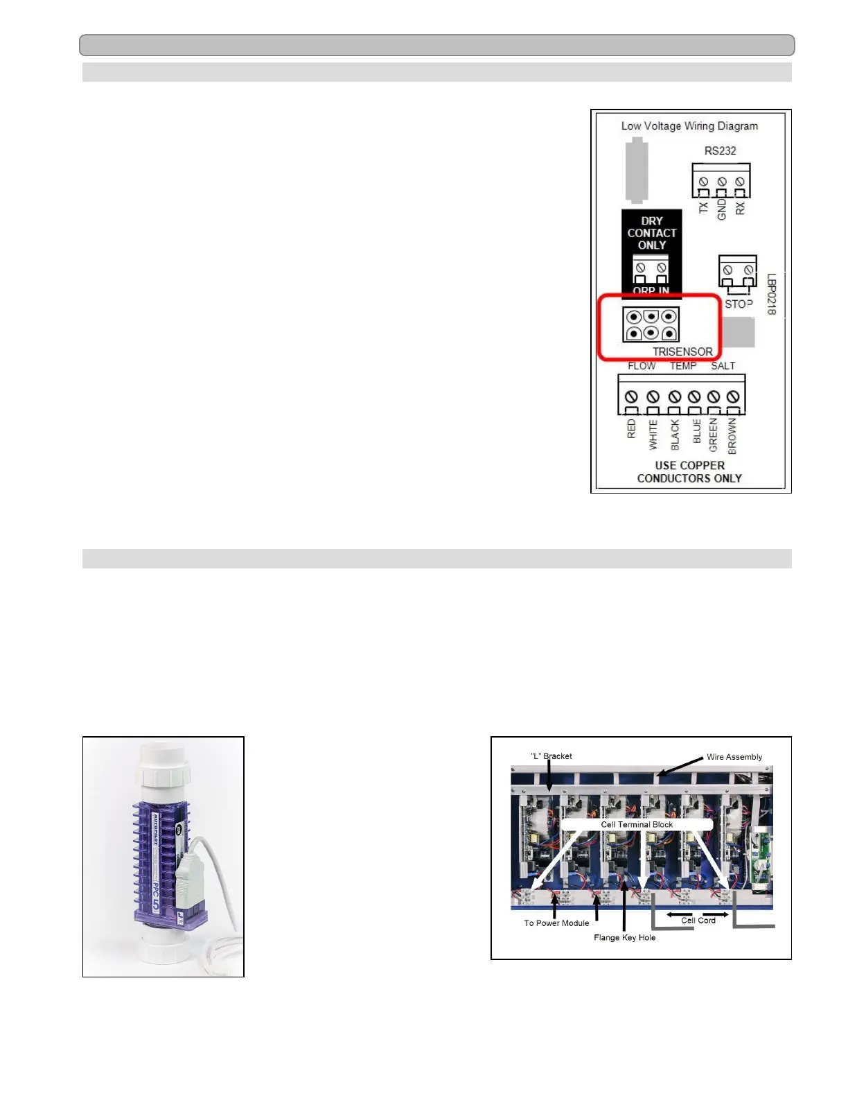
8.10 Low Voltage Wiring
8.10.a Tri-sensor Cord
LBP0218
Figure 21
The Tri-sensor cord is connected through the electrical access box.
1.
Remove front access panel.
l The access panel is secured by four (4) screws. Remove all
four (4) of the screws
l Lift off the panel to view the electrical access box
2.
Remove the panel on the side of the cabinet to expose the electrical
access box.
3.
On the underside of the cabinet is another small access panel.
Remove this panel.
4.
Thread the Tri-sensor cord through the strain relief connector and
attach the rectangular metal plate.
5.
Align the Tri-sensor connector on the end of the cord to the
connector on the side electrical panel.
6.
When the Tri-sensor is attached, replace the small rectangular plate
on the underside of the cabinet.
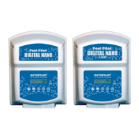
8.10.b Cell Cord
Depending on the model, there will be two (2) – six (6) cell cords provided with the complete
system. The cell cords are prewired to the unit at the factory.
1.
The cell cord should be seated firmly onto the cell terminals.
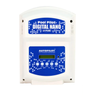
2.
The other end of the cell cord attaches to the terminal block at the base of the control center. The black
wire from the cell cord is matched to the center terminal (black wire) of the control center wiring.
3.
The other two wires from the cell cord (red and white wires) can be connected to either of the outer
terminals (red wires) of the terminal block.
Cell Cord Connection-Cell
Figure 22
Cell Cord Connection-Terminal Block
Figure 23