Page - 30
Note: To avoid mismatching or crossing cell connections, each cell and cell cord should be
appropriately labeled with markings to identify them. AquaCal AutoPilot, Inc. recommends using
a marking system of A-1, A-2, A-3, etc. for each cell and cell cord, then marking the power supply
with PS-A and Tri-sensor with TS-A, etc. If additional units are used, they should be labeled B-1,
B-2, PS-B, TS-B, etc. to guarantee that no wires or cords become crossed.
8.11 ORP Connection
ORP Connections
When an ORP chemical controller is interfaced to your Pool Pilot
®
Professional, and does not
provide a Dry Contact ORP signal, the AutoPilot
®
ORP Relay Box (part # 110-ORP) is required.
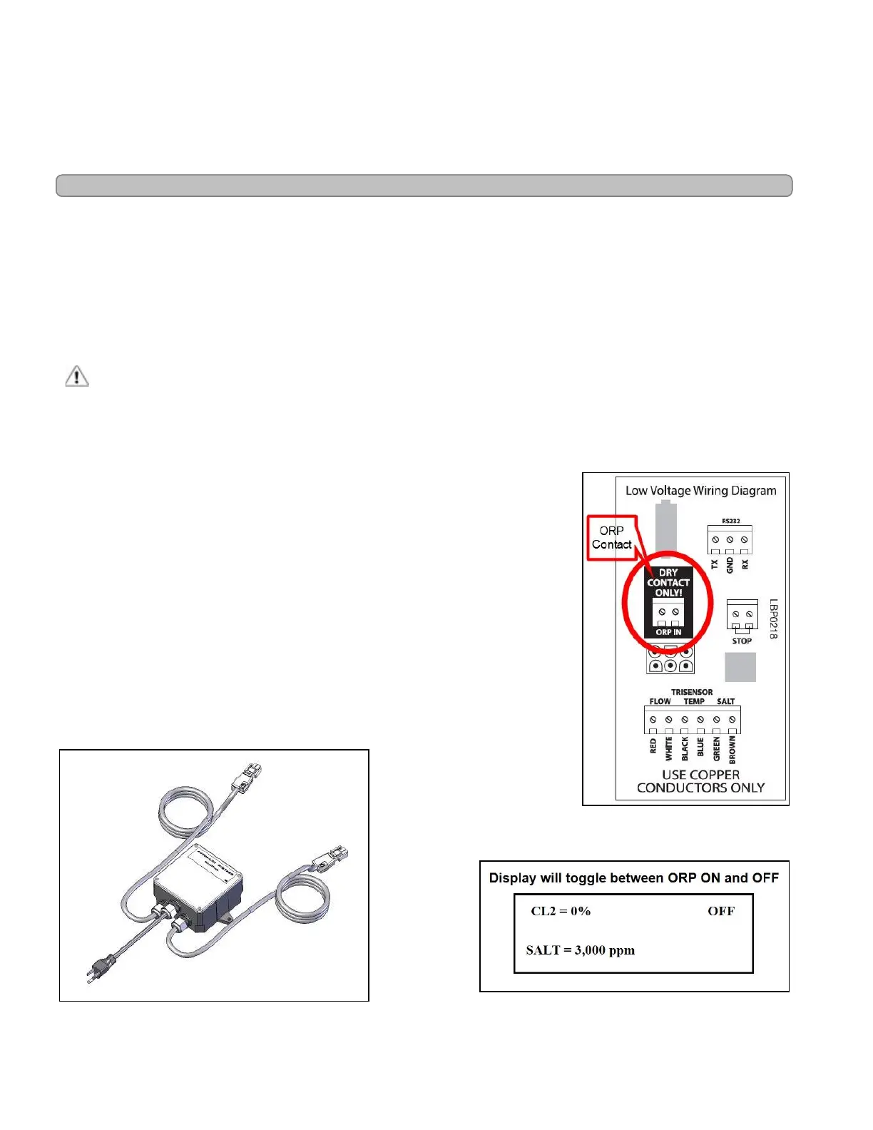
For ORP controllers with an ORP Dry Contact Signal, it can be wired directly to the units ORP IN
terminal. The controller will control chlorine output. Once connected, as the controller
measurement falls below the set point, the unit is activated to produce chlorine until the set point
is satisfied. Check your local commercial guidelines for minimum and maximum ORP levels.
CAUTION - Failure to heed the following may result in equipment damage.
l The remote connections are compatible with either dry contact closure or solid-state relay. Do not
energize these inputs! Damage to the control panel will occur and the warranty will be voided.
LBP0218
Figure 24
Connecting the Optional ORP Controller Relay
1.
Turn off power to the unit by the power circuit breaker. Confirm there
is no power going to the unit.
2.
Remove the front cover plate and side access panel where the Dry
Contact Only / ORP IN connection is located.
3.
Cut off the connector and strip the wire casing ½″ inch to expose the
wires and connect the ORP controller wires to the terminal block
marked ORP IN.
4.
Adjust the purifier output level to 0%. The controller will takeover
purifier output. The display will show as seen in Figure 26.
ORP and pH controller supplemental instructional sheets are
provided when the optional controller is ordered.
ORP Relay Box
Figure 25
Display w /ORP Connection
Figure 26