Controls
10
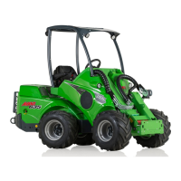
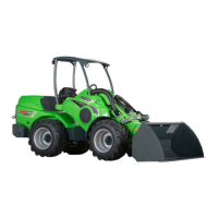
200 Series
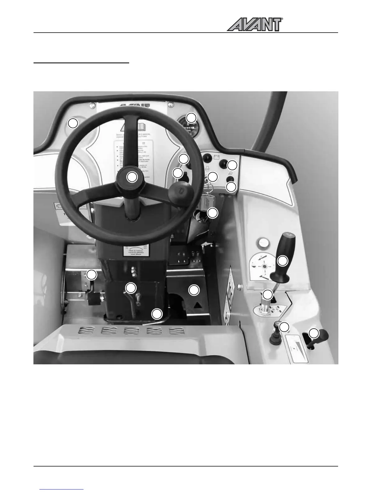
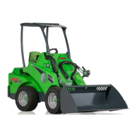
OPERATING CONTROLS
Following picture shows the location of operating controls. The location and function of controls may be
slightly different in different models, see following pages.
1
12
2
3
4
5
6
7
8
9
10
11
13
14
15
16
1. Steering wheel
2. Hour meter
3. Ignition switch
4. Signal horn
5. Light switch
6. Fuse box
7. Control lever of boom and bucket
8. 12 V outlet
9. Hand throttle lever
10. Choke
11. Drive pedal, right: drive forward
12. Drive pedal, left: drive backward
13. Parking brake handle
14. Lockable auxiliary hydraulics control pedal
15. Oil temperature gauge (optional extra)
16. Drive circuit release valve
17. Work light indicator
17