2. Grasp the SFP+ transceiver between your thumb and forefinger.
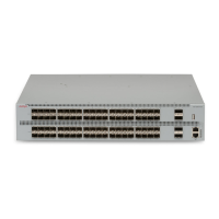
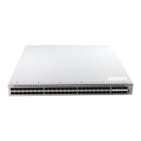
3. Insert the device into the port on the module.
Depending on the module type, you must insert some SFP+ transceivers into the port with
the bail facing up and some SFP+ transceivers with the bail facing down.
Warning:
Risk of equipment damage
SFP+ transceivers are keyed to prevent incorrect insertion. If the SFP+ transceiver
resists pressure, do not force it; turn it over, and reinsert it.
Apply a light pressure to the SFP+ transceiver until the device clicks and locks into position
in the module.
4. Remove the dust cover from the SFP+ optical bores, and insert the fiber optic cable.
Example
Job aid
Depending on the transceiver manufacturer, the SFP+ transceiver uses bail-latch type of locking
and extractor mechanism.
The following figure shows typical mechanism used on SFP+ transceivers; other locking and
extractor mechanisms exist. SFP+ transceivers are similar to SFP transceivers in physical
appearance. In the following figure, the SFP+ transceiver still contains the bore plug. Pull the bail to
release the device.
SFP+ transceivers
April 2016 Installing Transceivers and Optical Components on Avaya ERS 4900 and 5900
Series 43
Comments on this document? infodev@avaya.com

 Loading...
