- 24 -
connected" without showing any zoning. The zoning status set remains stored until the next time the
system is disconnected
3) Disconnection
To disconnect the system, slide the key in with the control panel fully or partially connected. The green
LED switches off. The AP also supplies important information about the status of the system with "fault"
and "alarm" indications. These indications are summarised and have the purpose of making the user
check the control panel pilot lights to inspect in detail the events that have occurred. The table below
shows the way this information is shown along with its meaning.
Green L1 LED : flashing. This groups one or more of the following:
• flat battery;
• one or more lines open (indication displayed only with the control panel
disconnected);
• one or more lines excluded though the relative zone exclusion pushbuttons
located on the control panel (indication displayed only with the control panel
disconnected).
Red LED L3: flashing. Indicates that one or several zones of the system connected have detec-
ted an alarm. (indication displayed only with the control panel connected)
Fault
Alarm
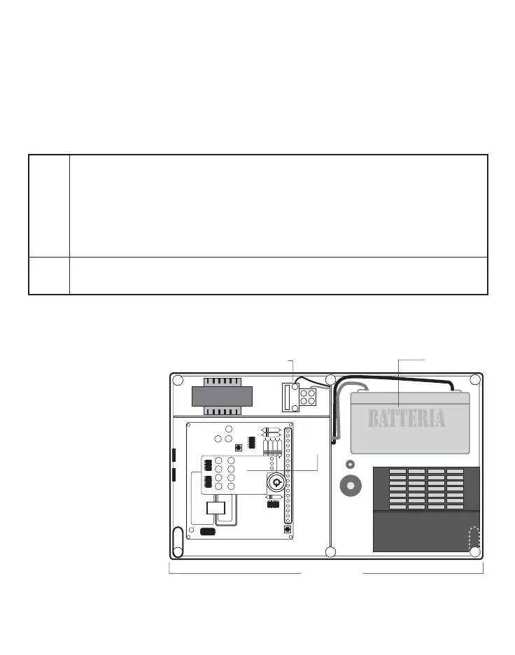
MAINS AND BATTERY CONNECTIONS
For the control panel operation, a 12v/6.5Ah backup battery must be connected and housed inside the
control panel in its special
seat, as shown in figure 4.
Connect the two 230Vac
mains voltage wires to the
two terminals, as shown in
figure 4.
CONNECTION TERMINAL BLOCK (page 30) AND APPLICATION DIAGRAM (page 1b)
The terminal block is composed of No. 21 screw terminals with bracket tightening of the conductor;
rating 2.5 mm
2
.
Main
board
Wall fixing hole
Battery seat
230 vac connection
terminal block
Fig. 4