600-00081-000 Rev 07
-5- FlightMax
Entegra PFD
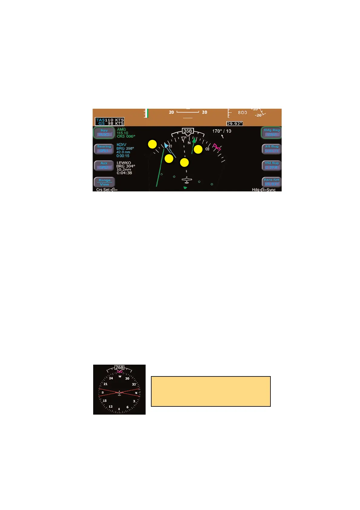
5. Projected Track Line- The dashed white projected track line
originates from the aircraft present position symbol and terminates
at the triangle along the outer edge of the compass rose. It dis-
plays a projection of the current ground track of the aircraft.
6. Course Deviation Indicator (CDI)- The green single-line CDI
displays deviation from the set or desired course.
7. Bearing Pointer- The blue dual-line bearing pointer is associated
with the Bearing source and displays the current bearing to the
Bearing waypoint (GPS1 or GPS2) or bearing to the station (VLOC1
or VLOC2). A bearing pointer will not be displayed if the VLOC
source is tuned to an ILS or LOC station. NOTE: This feature
requires that at least one GPS/VHF navigator be installed.
8. Compass Rose- In both 360 degree full view and 120 arc view,
the minor graduation marks represent 5 degrees, major
graduation marks represent 10 degrees, with every 30 degrees
labeled. The outer edge of the compass rose is marked with refer-
ence marks every 45 degrees.
EHSI Arc View
HSI Symbology System Overview
5
8
7
6
Until a flight plan is activated in GPS/Nav
1, the HSI will show a red X in place of
the CDI.
 Loading...