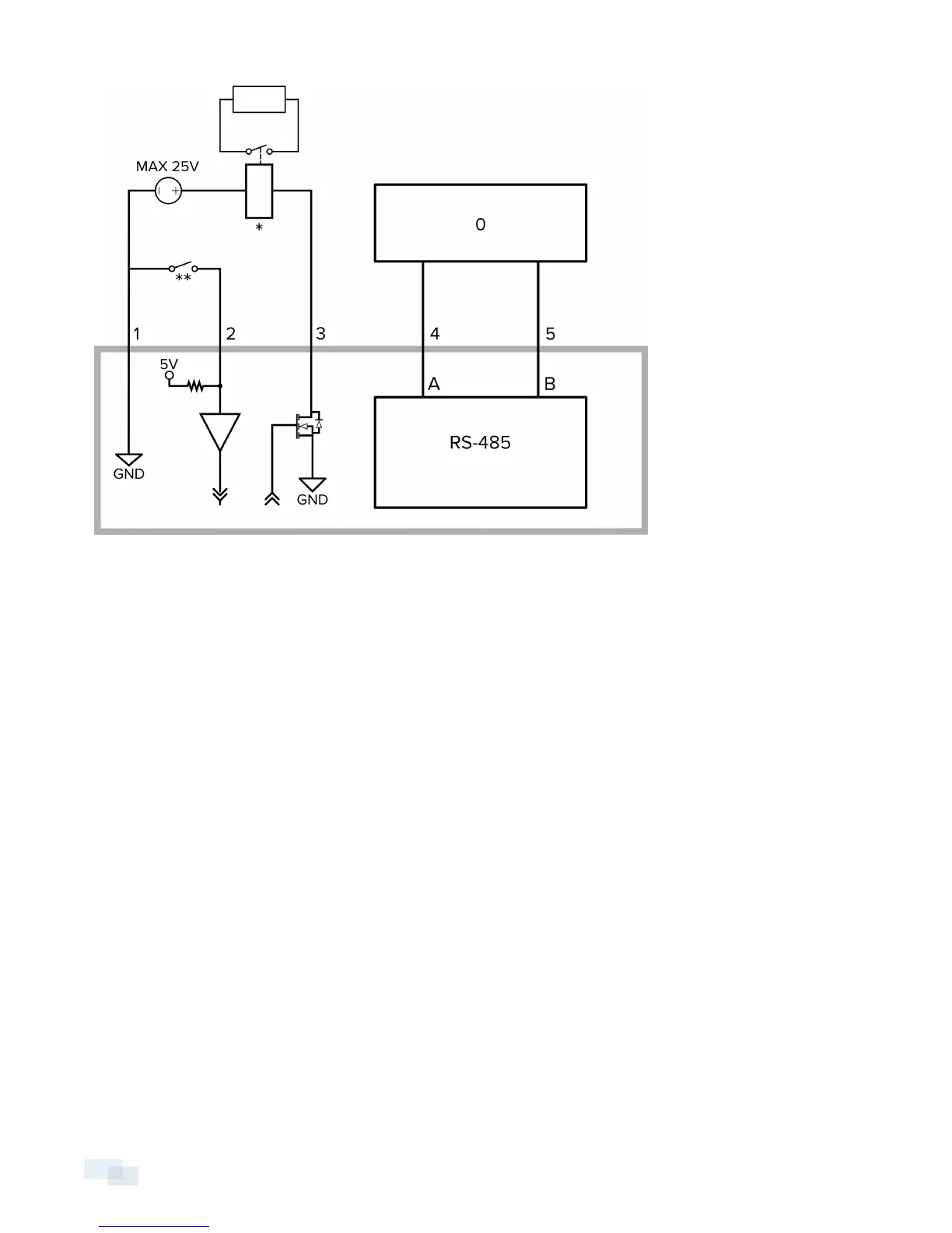
1. Ground
2. Relay Input — To activate, connect the Input to the Ground pin. To deactivate, leave disconnected or
apply between 3-15 V.
3. Relay Output — When active, Output is internally connected with the Ground pin. Circuit is open when
inactive. Maximum load is 25 VDC, 120 mA.
4. RS-485 A — Non-inverting RS-485 pin for controlling external equipment.
5. RS-485 B — Inverting RS-485 pin for controlling external equipment.
6. 0 — External Device
7. * — Relay
8. ** — Switch
Connecting to Microphones, Speakers and Video Monitors
The camera can be connected to an external microphone and speaker through the A/V connector. The camera
only supports line level mono audio input.
1.0 and 2.0 megapixel models can also be connected to an external monitor through the same A/V connector.
The video output signal is determined by the camera flicker control setting. When the camera flicker control is
set to 60 Hz, the video output signal is NTSC. When the flicker control is set to 50 Hz, the video output signal is
PAL. Use the camera web browser interface to configure the camera’s flicker control in the Image and Display
setup.
All models of the camera use a mini-jack (3.5 mm) audio/video connector. The pinout for the connector is shown
in the following diagram:
9 Connecting to Microphones, Speakers and Video Monitors
 Loading...