Do you have a question about the Avigilon H5A Series and is the answer not in the manual?
Formal summary of the disclaimer text and limitations of liability.
Details essential safety warnings, including electrical hazards and proper handling instructions.
Explains FCC compliance rules for the device and potential interference.
Provides guidelines for product disposal and recycling, including EU specific instructions.
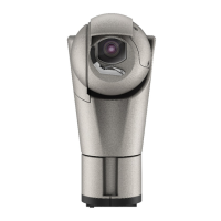
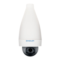
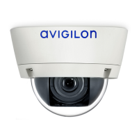
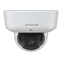
Illustrates and describes the front, rear, bottom, and DIN rail views of the main unit.
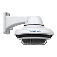
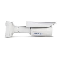
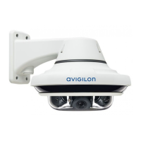
Illustrates and describes the micro bullet and right angle imagers, including their components.
Illustrates the optional accessory flat bracket and its mounting clips and slots.
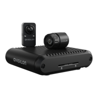
Lists required components and cables for setting up the modular camera system.
Provides recommendations for camera mounting and aiming for optimal analytics performance.
Details recommended practices for using HD BNC cables to ensure signal quality and IP66 rating.
Lists tools and materials needed for installing the main unit, not included in the package.
Lists the items included in the main unit package.
Details various mounting options for the main unit: surface, wall, and DIN rail.
Details how to connect network and imager cables to the main unit.
Explains how to connect external DC power to the unit when PoE is unavailable.
Describes how to connect external audio and input/output devices via the I/O connector block.
Lists necessary tools and materials for micro bullet imager installation.
Lists the items included in the micro bullet imager package.
Instructions for using the L-bracket to mount the micro bullet imager on a flat surface.
Details various ways to mount the imager: L-bracket, through surface, and on metal sheets.
Lists necessary tools and materials for right angle imager installation.
Lists the items included in the right angle imager package.
Details various mounting methods: through surface, directly to surface, and with bracket.
Guides on creating the first administrator user for camera access.
Details assigning an IP address and accessing the live video stream via web browser or VMS.
Covers onboard storage, general camera settings, and Wi-Fi adapter usage.
Lists other guides for further setup and usage information.
Explains the meaning of the green connection status LED for network connectivity.
Describes the LEDs indicating the status of HD BNC connections to imagers.
Provides solutions for common network and imager connection issues indicated by LED behavior.
Instructions for cleaning the micro bullet imager lens bubble with recommended materials.
Guidelines for cleaning the exterior of the imager and main unit bodies.
| Model | H5A Series |
|---|---|
| Sensor Type | CMOS |
| Lens Type | Varifocal |
| Day/Night | Yes |
| IR Distance | Varies by model |
| WDR | Yes |
| Video Compression | H.265, H.264 |
| Frame Rate | Up to 30 fps |
| Ethernet | 100BASE-TX |
| Power | PoE or 12VDC |
| Operating Temperature | -40°C to +60°C (-40°F to +140°F) (depending on the model) |
| Ingress Protection | IP66 |
| Impact Rating | IK10 |
| Dimensions | Varies by model |
| Weight | Varies by model |