4. Power the camera using one of the following methods:
l
Power over Ethernet (PoE) Class 3 — If PoE is available, the LEDs will turn on. PoE, IEEE 802.3af
Class 3 is sufficient to power the modular camera main unit and up to two connected imagers.
l
External Power — Connect an external 12 V DC power source to the power connector block.
For more information, see Connecting External Power below.
The status LEDs turn on when the camera receives power.
Connecting External Power
If PoE is not available, the camera needs to be powered through the removable power connector block. Refer
to the Main Unit Overview section for the location of the power connector block.
To connect power to the power connector block, complete the following steps:
1. Remove the power connector block from the camera.
2. Remove the insulation from ¼” (6mm) of the power wires. Do not nick or damage the wires.
3. Insert the two power wires into the two terminals on the power connector block. The connection can
be made with either polarity.
Use a small slotted (5/64” or 2mm blade width) screwdriver to loosen and tighten the terminals.
4. Attach the power connector block back into the camera.
WARNING — This product is intended to be supplied by a UL Listed Power Unit marked “Class 2” or
“LPS” or “Limited Power Source” with output rated 12 VDC, 11.5 W min. or PoE, 11.5 W min.
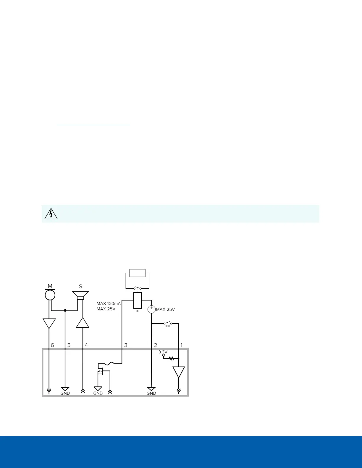
Connecting to External Audio and I/O Devices
External audio and I/O devices are connected to the camera through the audio and I/O connector block. The
pinout for the connector block is shown in the following diagram:
Connecting External Power 23
 Loading...