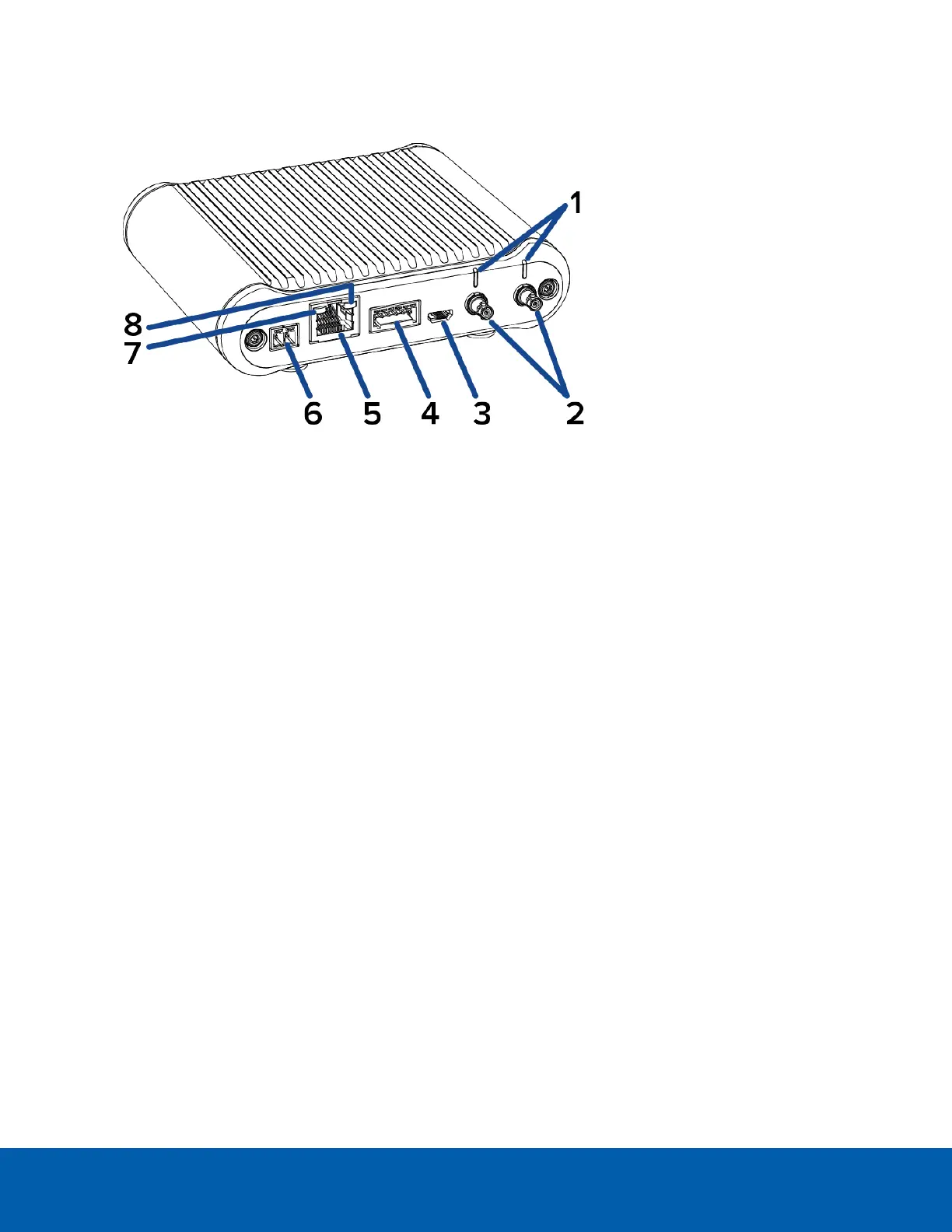
Rear View
1.
Imager connection LEDs (x2)
LEDs that provide information about imager device connections. For more information, see Imager
Connection LED Indicators on page53.
2.
Imager HD BNC connectors (x2)
HD BNC cable connections for connecting the modular camera main unit to up to two imager modules.
3.
Micro USB port
Accepts a micro USB to USB adapter. Only required when using the Avigilon USB Wi-Fi Adapter.
4.
I/O connector block
Provides connections to external input/output and audio devices.
5.
Ethernet port
Accepts an Ethernet connection to a network. Server communication and image data transmission
occurs over this connection. Also receives power when it is connected to a network that provides
Power over Ethernet.
6.
Power connector block
Accepts an external DC power connection when Power over Ethernet is not available.
7.
Link LED indicator
Amber LED indicates if there is an active connection in the Ethernet port.
8.
Connection status LED indicator
Green LED provides information about device operation. For more information, see Connection Status
LED Indicator on page52.
Rear View 9
 Loading...