8 ESP Serial Hub Installer/User Guide
Table 2.4 lists the pin assignments for the RS-422 and RS-485 interfaces.
4 DTR Data Terminal Ready Output
5 GND Ground N/A
6 DSR Data Set Ready Input
7 RTS Request to Send Output
8 CTS Clear to Send Input
9 N/C N/C N/A
Not supported: RI, RS-422 RTS and CTS differential control signals.
Unused pins (labeled N/C) should not have wires attached to them. Floating wires could cause unbalanced
noise, shorten overall distances and degrade performance.
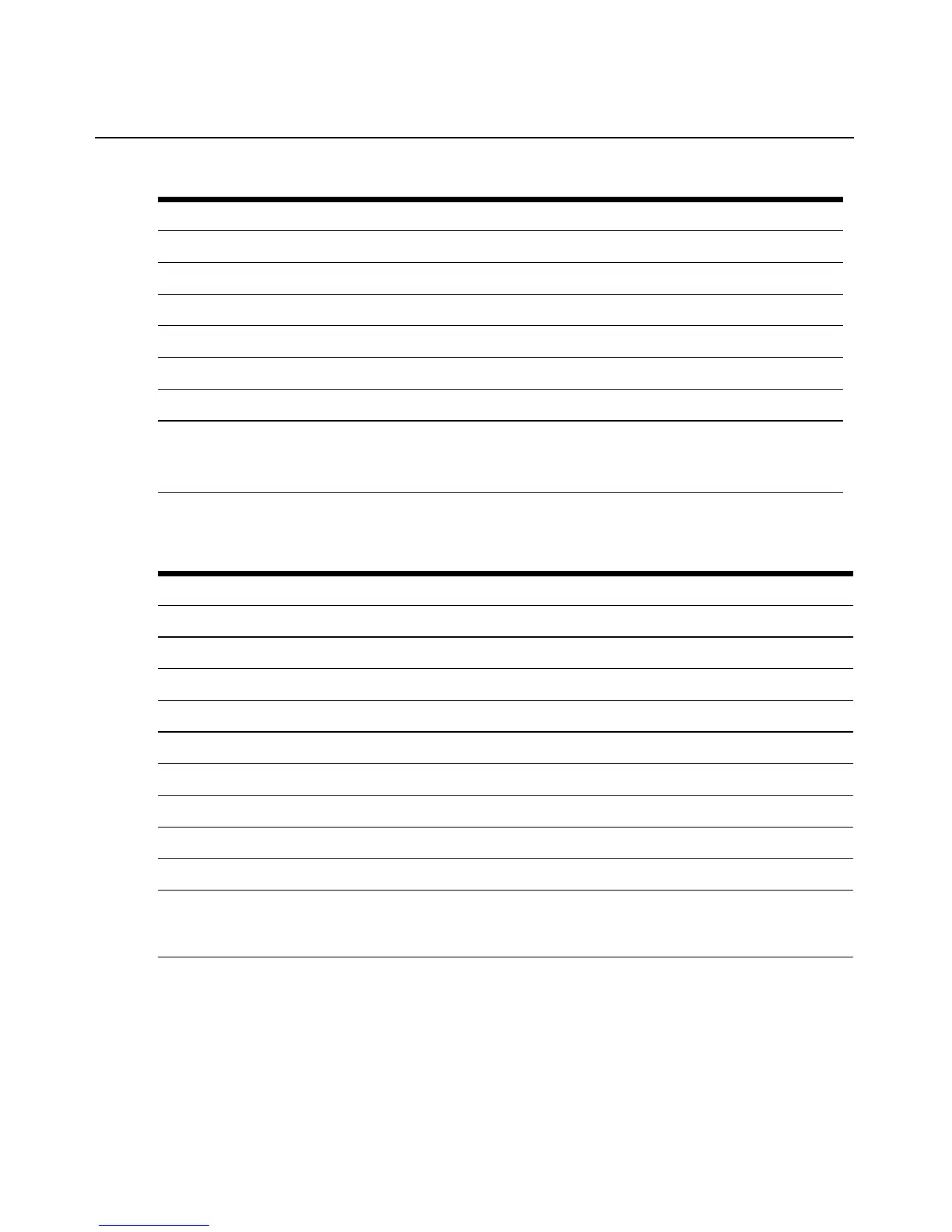
Table 2.4: RS-422 and RS-485 Serial Port Pin Assignments
Pin Number RS-422/485 * Description Direction
1 RxD (+) Receive Data (pos) Input
2 RxD (-) Receive Data (neg) Input
3 TxD (+) Transmit Data (pos) Output
4 TxD (-) Transmit Data (neg) Output
5 GND Ground N/A
6 DSR (RS-232) Data Set Ready (remains RS-232) Input
7 RTS * (RS-232) Request to Send (remains RS-232) * Output
8 CTS * (RS-232) Clear to Send (remains RS-232) * Input
9 N/C N/A N/A
* The RS-485 interface is implemented by using special cables that connect RxD(+) to TxD(+) and RxD(-) to
TxD(-), thus providing the 2-wire bidirectional interface. In addition, pins 7 and 8 should be jumpered together
to signal that the port is configured for RS-485. Pins 7 and 8 should be left open for an RS-422 configuration.
Table 2.3: RS-232 Serial Port Pin Assignments (Continued)
Pin Number RS-232 Description Direction