5
CHAPTER
2
Hardware Installation and
Network Configuration
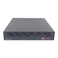
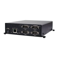
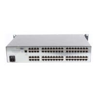
ESP Serial Hub Kit Contents
• ESP serial hub.
• SuperSerial CD-ROM.
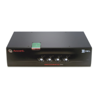
• For ESP-2 MI and ESP-4 MI hubs: External power supply (PS) with attached PS-to-unit barrel
connector. The line cord for the power supply is appropriate to the intended country
of operation.
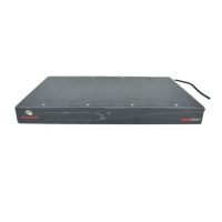
• For ESP-8 MI and ESP-16 MI hubs: AC power cord.
Modular adaptors are available from Avocent; see Adaptors on page 77.
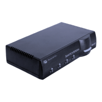
LEDs and Buttons
All LEDs and buttons are on the front of the ESP serial hub.
Table 2.1: LEDs and Buttons
Item Models Description
POWER All The POWER LED is lit when the hub is connected to a power source.
ONLINE All
The ONLINE LED is lit (not blinking) when the hub’s self-test and initialization
procedures have completed successfully.
On ESP-4 MI hubs at power up, the LED will blink rapidly until the hub is
initialized, then it will be lit (not blinking). If a problem occurs, the LED will turn off.
10
ESP-2 MI and
ESP-4 MI
The 10 LED is lit when the hub is connected to a 10 Mbps LAN, and the 100 LED
blinks when traffic is present on the 10 Mbps LAN.
100 All
The 100 LED is lit when the hub is connected to a 100 Mbps LAN.
On ESP-2 MI and ESP-4 MI hubs, the 10 LED blinks when traffic is present on
the 100 Mbps LAN.
LINK
ESP-8 MI and
ESP-16 MI
The LINK LED is lit when the hub establishes a connection to the network.