6 ESP Serial Hub Installer/User Guide
Physical Interfaces
Table 2.2 summarizes the ESP serial hub physical interfaces and connector information. Details
follow the table.
All of the serial ports on the ESP-2 MI, ESP-4 MI and ESP-8 MI hubs may be configured to
support the following physical interfaces:
• RS-232 DTE signaling
• RS-422 signaling (default)
• RS-485 2-wire half duplex (HD) signaling
On ESP-16 MI hubs, the first eight serial ports (ports 1-8) may be configured to support any of the
physical interfaces noted above. The remaining eight ports (ports 9-16) are dedicated RS-232 ports.
By default, RS-232 is enabled on all serial ports.
For ESP-2 MI hubs, internal jumper settings select the physical interface for each port. See
Changing the Serial Port Interface on ESP-2 MI Hubs on page 75.
TRAFFIC
ESP-8 MI and
ESP-16 MI
The TRAFFIC LED blinks when there is traffic on the LAN.
RESET All
Pushing (and holding for ESP-8 MI and ESP-16 MI hubs) the RESET button
reboots the hub; see Resetting on page 13.
INIT All
Pushing and holding the INIT button restores the hub to factory defaults; see
Reinitializing on page 13.
Table 2.1: LEDs and Buttons (Continued)
Item Models Description
Table 2.2: Physical Interface and Connector Summary
Model
Connector type
and location
Physical interfaces can be configured on Where physical
interface is
configured
RS-232 RS-422 RS-485
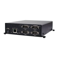
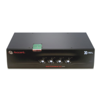
ESP-2 MI
DB-9
Front of hub
all ports (1-2) all ports (1-2) all ports (1-2) hardware
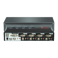
ESP-4 MI
DB-9
Front of hub
all ports (1-4) all ports (1-4) all ports (1-4) software
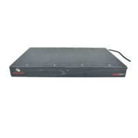
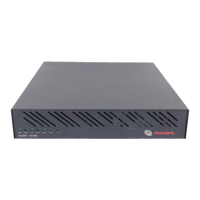
ESP-8 MI
RJ-45
Back of hub
all ports (1-8) all ports (1-8) all ports (1-8) software
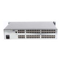
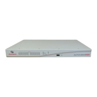
ESP-16 MI
RJ-45
Back of hub
all ports (1-16) only ports 1-8 only ports 1-8 software