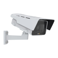
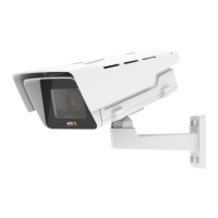
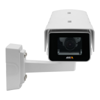
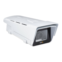
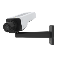
AXIS P1368-E Network Camera
Digital output - For connecting external devices such as relays and LEDs. Connected devices can
be activated by the VAPIX® Application Programming Interface or in the product’s webpage.
Digital input - For connecting devices that can toggle between an open and closed circuit, for
example PIR sensors, door/window contacts, and glass break detectors.
4-pin terminal block
Function Pin Notes
Specications
0 V DC (-)
1
DC ground 0 V DC
DC output
2
Can be used to power auxiliary equipment.
Note: This pin can only be used as power out.
12 V DC
Max load = 50 mA
Congurable
(Input or
Output)
3–
4
Digital input – Connect to pin 1 to activate, or
leave oating (unconnected) to deactivate.
0 to max 30 V DC
Digital output – Connected to pin 1 when
activated, oating (unconnected) when
deactivated. If used with an inductive load, e.g. a
relay, a diode must be connected in parallel with
the load, for protection against voltage transients.
0 to max 30 V DC,
open drain, 100 mA
26
Available from A1 Security Cameras
www.a1securitycameras.com email: sales@a1securitycameras.com