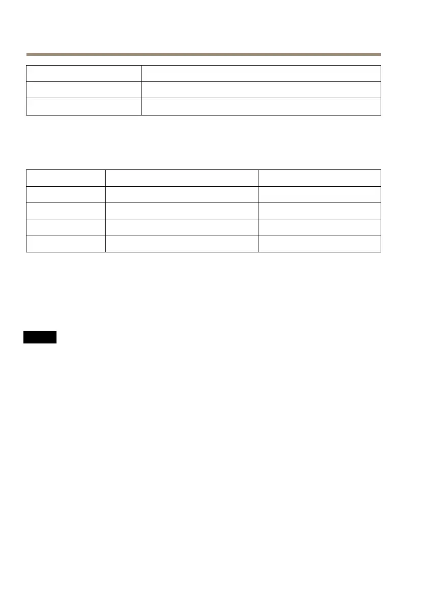
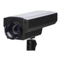
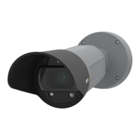
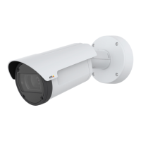
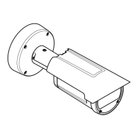
AXISQ1775NetworkCamera
PowerLEDIndication
Green
Normaloperation.
Amber
Flashesgreen/amberduringrmwareupgrade.
StatusLEDBehaviorandBuzzerSignalforLevellingAssistant
Forinformationonusingthecontrolbuttontostartlevellingofthecamera,seepage13.
Color
Buzzer
Cameraposition
Fixedgreen
Continuousbeep
Level
FlashinggreenFastintervalAlmostlevel
FlashingorangeMediumintervalNotlevel
Flashingred
Slowinterval
Farfromlevel
ConnectorsandButtons
Forspecicationsandoperatingconditions,seepage14.
NetworkConnector
NO NO
NO
TICE TICE
TICE
Duetolocalregulationsortheenvironmentalandelectricalconditionsinwhichtheproduct
istobeused,ashieldednetworkcable(STP)maybeappropriateorrequired.Allcables
connectingtheproducttothenetworkandthatareroutedoutdoorsorindemanding
electricalenvironmentsshallbeintendedfortheirspecicuse.Makesurethatthenetwork
devicesareinstalledinaccordancewiththemanufacturer’sinstructions.Forinformation
aboutregulatoryrequirements,seeElectromagneticCompatibility(EMC)onpage2.
I/OConnector
Usewithexternaldevicesincombinationwith,forexample,tamperingalarms,motiondetection,
eventtriggering,timelapserecordingandalarmnotications.Inadditiontothe0VDCreference
pointandpower(DCoutput),theI/Oconnectorprovidestheinterfaceto:
•Digitaloutput–ForconnectingexternaldevicessuchasrelaysandLEDs.Connected
devicescanbeactivatedbytheVAPIX®ApplicationProgrammingInterface,output
buttonsontheLiveViewpageorbyanActionRule.Theoutputwillshowasactive
(shownunderSystemOptions>Ports&Devices)ifthealarmdeviceisactivated.
•Digitalinput–Analarminputforconnectingdevicesthatcantogglebetweenanopen
andclosedcircuit,forexample:PIRs,door/windowcontacts,glassbreakdetectors,
12


 To Next Page