AXIS Q60-S Series
11. Make sure the clamp is in place, insert the braided shield coil into the ground clip and
tighten the screws.
NONO
NO
TICETICE
TICE
• The shields and the clamp surfaces shall be in full contact with each other so that the
multi-connector cable is grounded.
• Make sure that the multi-connector cable jacket is rmly secured by the clamp.
• Make sure all surfaces and contacts are clean and free from scrap shield material.
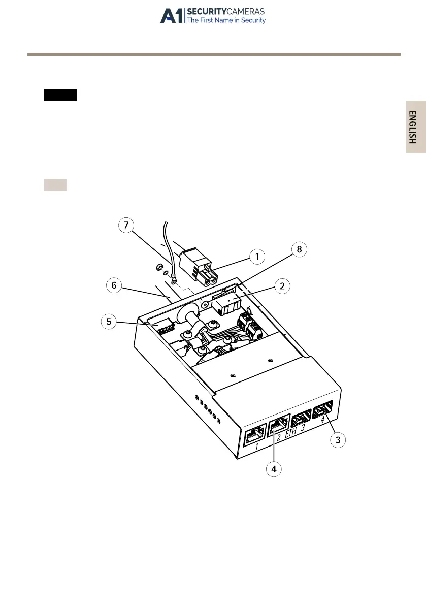
12. Connect the network cables to the external network connectors (RJ45, SFP) as required.
Note
An SFP module (not included) has to be used when connecting an optical ber cable.
1
Power cable (DC input)
2
Power connector (DC input)
3
Network connector SFP (external) (2x)
4
Network connector RJ45 (external) (2x)
5
I/O connector (external)
6
Multi-connector cable IP66
27
Available from A1 Security Cameras
www.a1securitycameras.com email: sales@a1securitycameras.com
 Loading...