AXIS Q87-E Installation Guide Page 11
ENGLISH
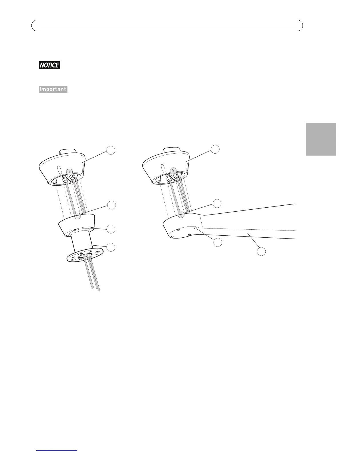
5. Attach the base to the bracket and tighten the screws (torque 4 Nm).
Apply Loctite 243
threadlocker on the screws.
The base can be attached to the bracket in four different positions. Use the alignment indicators on the dif-
ferent units to find a suitable position that allows access to the configuration board, which can be opened
for easy access to the network connector, see illustration on page 12. This is useful for troubleshooting or
for connecting an Axis installation display. The dip switches are configured with the correct PTZ protocol in
the factory and do not need to be changed.