Main Assembly
8
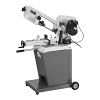
Fig 04-05
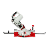
Fig 06-07-08
1
Table insert
Table shipment bolt
Tilt quadrant
Pre-drilled hole
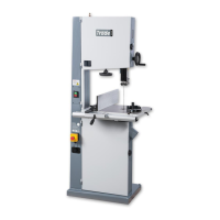
Fig 09-10
16 17
18
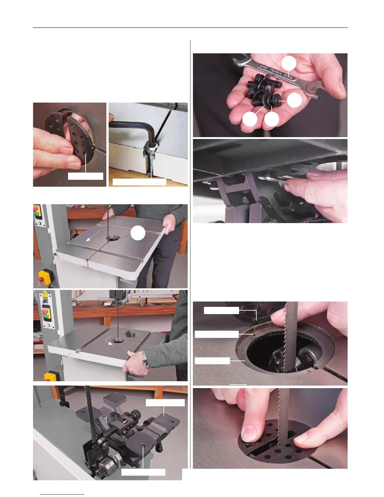
Fig 11-12
Table recess
Machined hole
Insert pin
Step 1 Remove the table insert and the table shipment
cap head bolt and nut and place aside, see figs 04-05. Lift the
table (1), slide the blade through the table slot, rotate the table
round and lower the table on to the tilt quadrant assembly, see
fig 06-07. Line up threaded holes with the pre-drilled holes in
the tilt quadrant, see fig 08.
Step 2 Place a spring/washer (16 -17) over each M8 threaded
bolt (18), see fig 09 and lightly tighten the four bolts in position,
see fig 10. Note DON’T FULLY TIGHTEN at this point.
Step 3 Replace the table insert by lining up the two pins in
the insert with the machined holes in the recess to the centre
of the cast iron table. Push firmly down, see figs 11-12.
14
 Loading...