3
REV. 1/5/2018 INSTAX-GMLAN29-SWC
CONNECTIONS TO BE MADE
Attention! This interface will work with models that are either non-amplified, analog amplified,
or digital amplified. Please follow the instructions carefully for your model vehicle. Failure to
do so will result in either no sound, or low sound. If you are unsure if your vehicle is factory
amplified or not, please contact your local dealership.
For models
without
an amplifier:
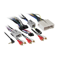
From the 16-pin harness with stripped leads to the aftermarket radio:
• Connect the Red wire to the accessory wire.
Note:
If installing an AX-LCD (sold separately), there will be an accessory wire there to
connect as well.
• If the aftermarket radio has an illumination wire, connect the Orange/White wire to it.
• If the aftermarket radio has a mute wire, connect the Brown wire to it. If the mute wire is
not connected, the radio will turn off when OnStar is activated.
• Connect the Gray wire to the right front positive speaker output.
• Connect the Gray/Black wire to the right front negative speaker output.
• Connect the White wire to the left front positive speaker output.
• Connect the White/Black wire to the left front negative speaker output.
The following (3) wires are only for multimedia/navigation radios that require these wires.
• Connect the Blue/Pink wire to the VSS/speed sense wire.
• Connect the Green/Purple wire to the reverse wire.
• Connect the Light Green wire to the parking brake wire
• Tape off and disregard the following (5) wires, they will not be used in this application:
Blue/White, Green, Green/Black, Purple and Purple/Black.
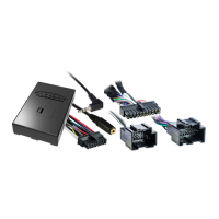
From the AX-GMLAN29-SWC harness to the aftermarket radio:
• Connect the Black wire to the ground wire.
• Connect the Yellow wire to the battery wire.
• Cut off the resistors from the Green, Green/Black, Purple, and Purple/Black wires below the
heat shrink.
• Connect the Green wire to the left rear positive speaker output.
• Connect the Green/Black wire to the left rear negative speaker output.
• Connect the Purple wire to the right rear positive speaker output.
• Connect the Purple/Black wire to the right rear negative speaker output.
• Ensure the (2) 4-pin Molex connectors are connected together.
Note:
The 4-pin to 4-pin resistor pad harness will not be used in this application.
• The Black/Yellow wire is used for OnStar level adjustment for models that do not come
equipped with steering wheel controls. Refer to the OnStar level Adjustment section for
further instructions.
• Connect the Red and White RCA jacks to the audio AUX-IN jacks of the aftermarket radio.
• The DIN jack is to be used with the optional AX-LCD (sold separately).
• Connect the Red wire to the accessory wire.
Note:
The relay attached to the AX-GMLAN29-SWC harness is only for audible turn signal
clicks. No extra steps are required to retain this feature, so leave the relay as-is.
Continue to 3.5mm jack steering wheel control retention
 Loading...