12 AB-6650
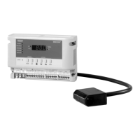
50* 72.5 47.5 50
100*
Clearance of the controller inside the rain-proof case / onto DIN rail
DIN rail
(unnecessary for the installation
inside the rain-proof case)
∗Note:
Hatched area shows 50 for rain-proof case
clearance required for 100 for DIN rail
the controller installation.
45 45
Figure 12. Clearance of the controller
2. 4-Electrode Sensor
Precautions for installation
• Install the 4-electrode sensor inside the sump of the
water tank or in a location (close to the tank) where
water flows well. Avoid installing the sensor close to
the water feeding point.
• Do not allow the 4-elctrode sensor to directly contact
the inner wall or the bottom of the water tank. Leave
approx. 10 cm away from the inner wall and from the
bottom for installation.
Installation procedure: 4-electrode sensor
Fix the 4-electrode sensor with φ2-4 mm wire inside the
sump of the water tank. Roll one end of the wire and
hang the 4-electrode sensor . (Lead the wire end
through the wire hanging tab of the sensor.) Tie the
other end of the wire to the cooling tower.
Cable of the 4-electrode sensor
Wire hanging tab of the 4-electrode sensor
4-elecrode sensor
Approx. 10 cm
Wire
(φ2-4 mm)
Circulating water
Approx. 10 cm
Figure 13. 4-electrode sensor installation in the water tank
3. Rain-Proof Case
Precautions for installation
• Install the rain-proof case (with the controller inside)
under the cooling tower, on a wall under an eave, and
other locations unexposed to direct sunlight and rain.
Installation procedure: Rain-proof case
Mount the rain-proof case on a wall with screws or on a
DN50 pipe with a u-bolt.
(See Fig. 4 for the mounting hole dimensions.)
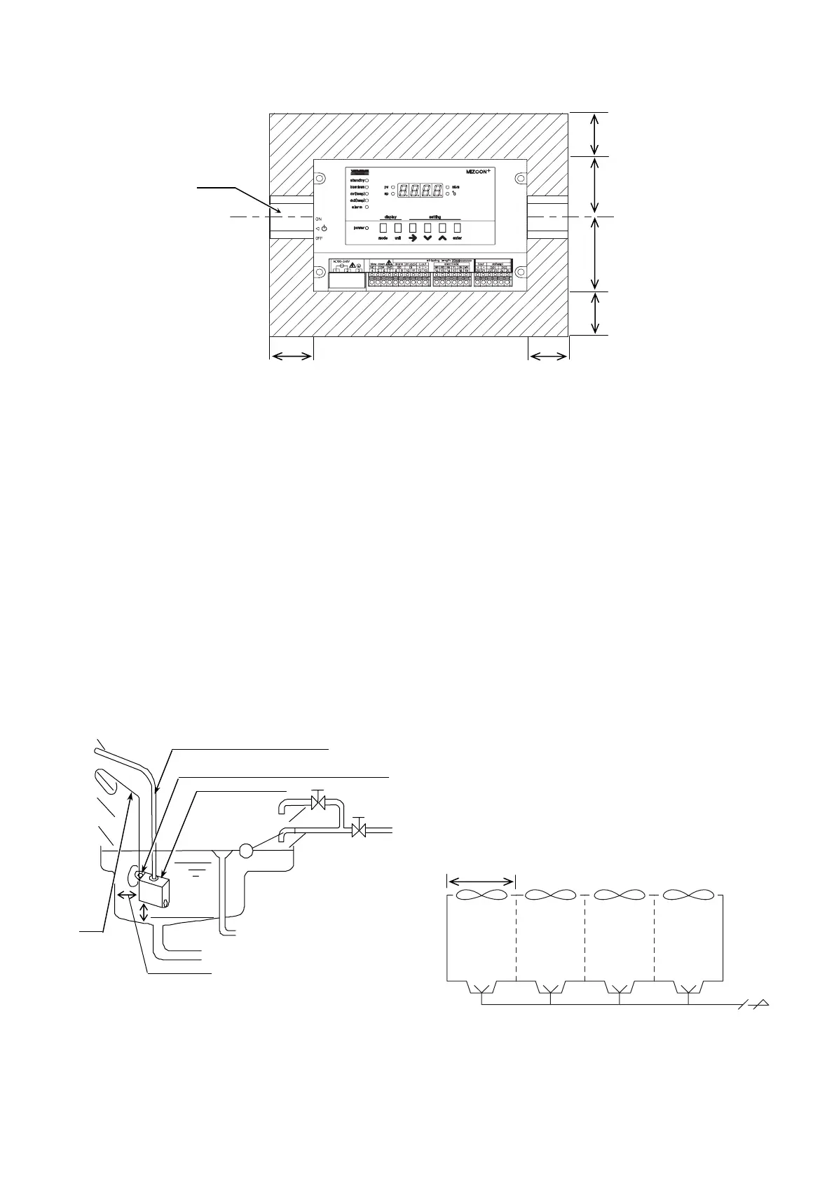
Fan Multiple Units Control
MIZCON Plus is not applicable to the multiple units
control of fans. That is, MIZCON Plus alone cannot
control the cooling tower composed of multiple cells
since the cooling water temperature of each cell may
differ.
Note:
Keeping to run the cooling tower fan until the cooling water
temperature drops down to the low limit increases the
chiller COP (Coefficient of Performance). Multiple units
control of the fans therefore is not recommended even with
an additional controller based on the representative
temperature.
1 cell
Cooling tower
Figure 14. Cooling tower composed of multiple cells
Blow-down wate
Sump of the
cooling water tank