13 AB-6650
Wiring
WARNING
• Be sure to disconnect the power source from MIZCON Plus before wiring the 4-electrode sensor. Electrical
shock may result.
CAUTION
• Before activating the MIZCON Plus, make sure all the wires are correctly connected. Faulty wiring may cause
equipment damage.
Wiring procedure
Power supply line (for M3.5 screw terminal connection):
Crimp the M3.5 crimp terminals on the wire ends, and connect them to the power supply terminal block.
Lines except the power supply line (for clamp terminal connection):
For the lines except the power supply line, the quick-ft screwless terminal blocks are provided. Follow the procedure
below for the wire connection.
1) Strip 10 mm sheath of a wire end.
2) Make sure that there is no wire fiber protruded from the bare wire (stripped part).
3) Insert the wire end while pressing the clamp release button using a slotted screwdriver. (Button-pressing force: 23 N)
4) Pull out the screwdriver with the wire end inserted. Then, lightly pull the wire to make sure it is tightly connected.
Again, make sure that there is no wire fiber protruded from the bare wire connected.
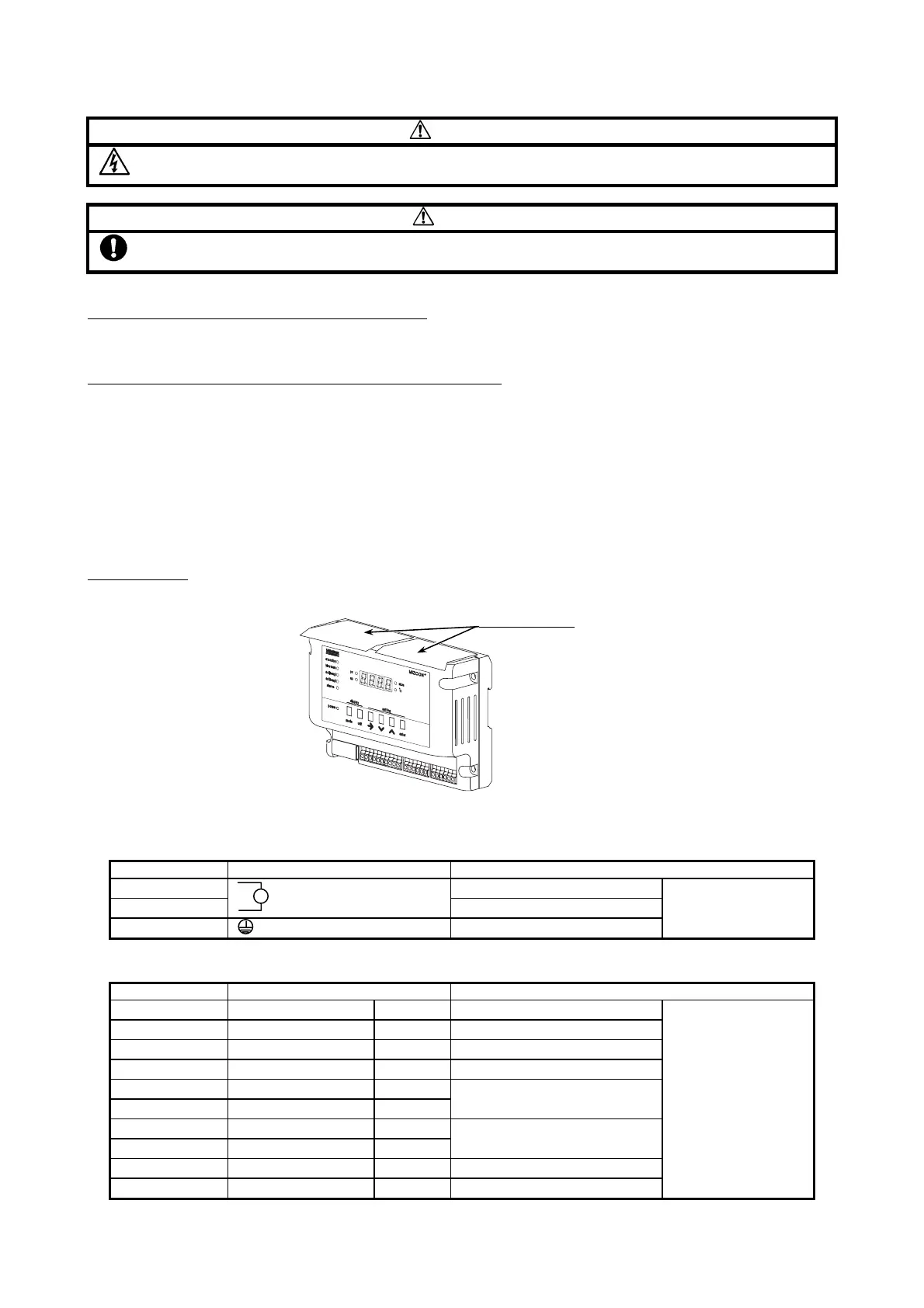
Protective sheet
:
After all the wires are completely connected, peel off the protective sheets until MIZCON Plus is activated.
Protective sheets
Figure 15. Protective sheets
Wire arrangement
1) Power supply (3 terminals)
Terminal number Terminal indication Description
1 Power supply input
2
Power supply input
3 Ground
Screw terminals
2) Signals 1 (10 terminals)
Terminal number Terminal indication Description
4 blow down NC Motorized ball valve N.C.
5 blow down COM Motorized ball valve common
6 blow down COM Motorized ball valve common
7 blow down NO Motorized ball valve N.O.
8 alarm DO
9 alarm DO
High limit alarm output
10 int.lock DI
11 int.lock DI
Interlock contact input
12 c.out + Conductivity 4-20 mA output (+)
13 c.out - Conductivity 4-20 mA output (-)
Quick-fit screwless
(clamp) terminals
∼