7-6
Chapter 7. SPECIFICATIONS
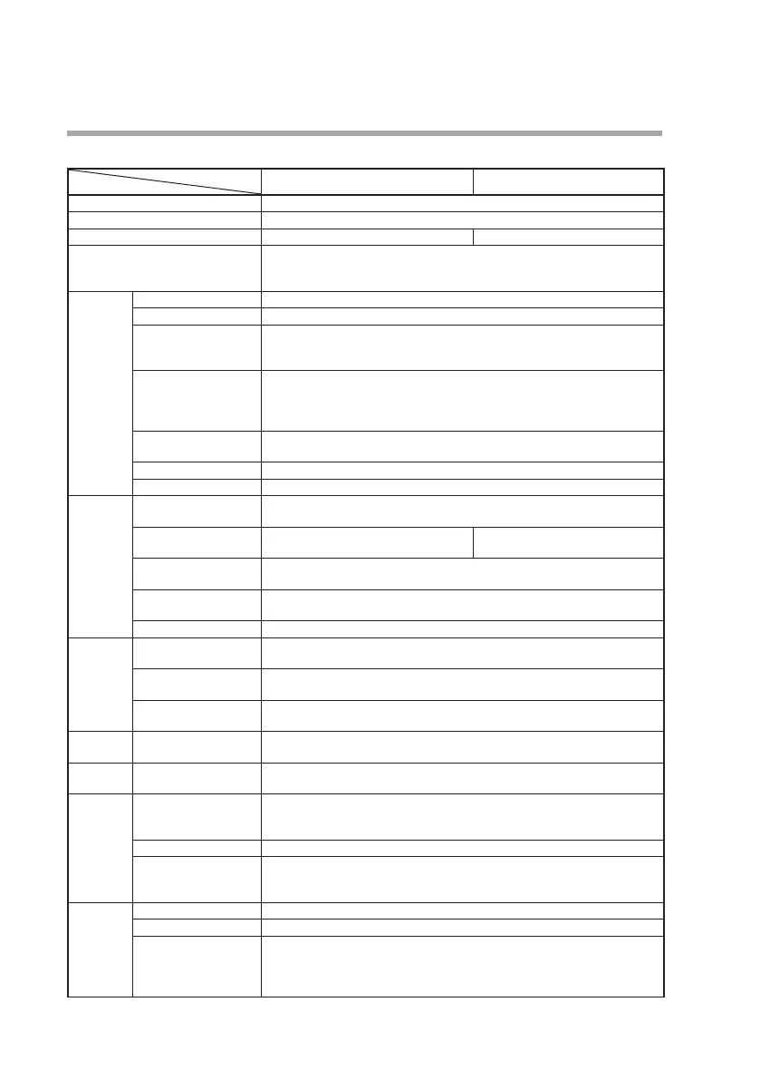
z MQV0050/0200
Model No.
Item
MQV0050 MQV0200
Valve type Proportional solenoid valve
Valve operation Normally closed when de-energized (N.C.)
Standard full-scale flow rate *
1
50.0 L/min (standard) 200 L/min (standard)
Gas types Hydrogen (H
2
), Helium (He)
Gas must be dry and not contain corrosive components (chlorine, sulfur, acid).
The gas must also be clean, not containing dust or oil mist.
Control Range 1 to 100 % FS (see “Gas type and control range” table (page 7-9))
Valve output update cycle
5 ms
Response
(at standard differen-
tial pressure)
Within 0.3 s at setting ±2 % FS (typ.)
(Control starts from the fully closed status or the setting is changed during
control.)
Accuracy
(at standard tempera-
ture and differential
pressure, Q: flow rate)
(1) ±2 % FS (80 % FS < Q ≤ 100 % FS)
(2) ±1 % FS (40 % FS < Q ≤ 80 % FS)
(3) ±0.5 % FS (0 % FS ≤ Q ≤40 % FS)
Repeatability (Q: flow rate)
(1) ±0.5 % FS (40 % FS < Q ≤ 100 % FS)
(2) ±0.25 % FS (0 % FS ≤ Q ≤40 % FS)
Temperature characteristics
0.06 % FS max. per 1°C
Pressure characteristics
0.2 % FS max. per 100 kPa
Pressure Standard differential
pressure
200 kPa (Inlet pressure: 200 kPa (gauge), outlet pressure: 0 kPa (gauge))
Required differential
pressure *
2
Hydrogen: 20 kPa
Helium: 40 kPa
Hydrogen: 100 kPa
Helium: 180 kPa
Operating differential
pressure range *
3
300 kPa max.
allowable inlet pres-
sure *
4
0.5 MPa (gauge)
Pressure resistance 1 MPa (gauge)
Temperature
Standard operating
temperature
+23 °C
Allowable operating
temperature range
–10 to +60 °C
Allowable storage
temperature range
–20 to +70 °C
Humidity Allowable operating
humidity range
10 to 90 % RH (condensation not allowed)
External
leaks
Helium leak rate Within 1 x 10
-6
Pa·m
3
/s
Flow rate
setup
Setup method (1) Key operation (2) External analog input
(3) MLP loader communications*
5
(4) RS-485 communications (3 wire-system)*
6
Setup resolution See “Gas type and control range” table (page 7-9).
External analog input Input range: 0 to 5 V DC/1 to 5 V DC/0 to 20 mA/4 to 20 mA (switchable)
Input impedance: 1 MΩ ± 10 % (for voltage input)
250 Ω ± 10 % (for current input)
Flow rate
display
Display method 7-segment LED 4 digits
Setup resolution See “Gas type and control range” table (page 7-9).
Indication accuracy (at
standard temperature
and differential pres-
sure; Q: flow rate)
(1) ±2 % FS ±1 digit (80 % FS < Q ≤ 100 % FS)
(2) ±1 % FS ±1 digit (40 % FS < Q ≤ 80 % FS)
(3) ±0.5 % FS ± 1digit (0 % FS ≤ Q ≤ 40 % FS)



 To Next Page