4
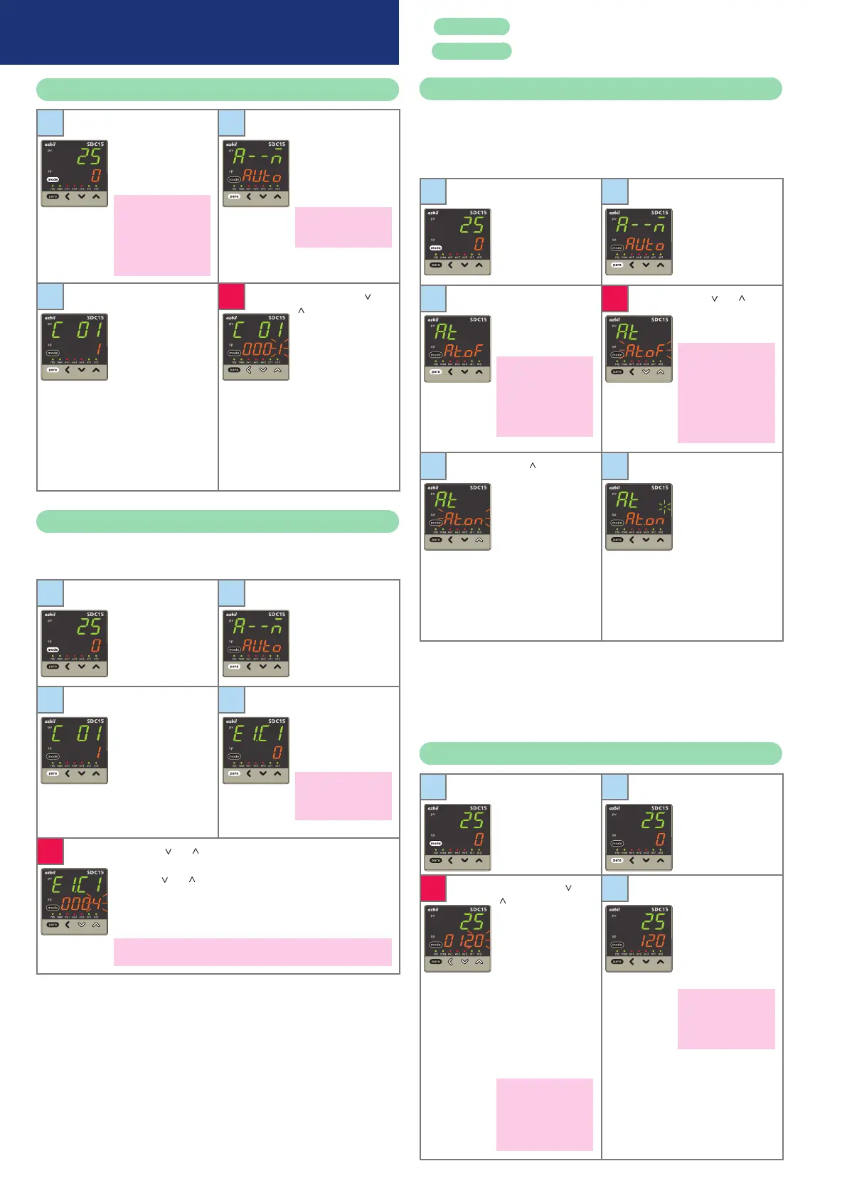
Setup of PV input range type
1
Start from the opera-
tion display (if neces-
sary press [mode]
once to get the op-
eration display).
If the sensor has not
been wired or is discon-
nected, an alarm for
abnormal PV input (any
one from
AL0
1
to
AL
1
1
)
may appear on the
upper display.
2
Press and hold [para]
for more than 2s to
get the parameter
setup display.
a--M
is shown on the
upper display.
In case of ON/OFF con-
trol,
r--r
appears on
the upper display.
3
Press and hold [para]
for more than 2s
again to get the
setup setting display.
The current set
value for
C0
1
(PV
input range type) is
displayed.
4
When the [<], [ ] or
[ ] key is pressed,
the rightmost digit
on the lower display
flashes. If no key is
pressed for more
than 2s after chang-
ing to the desired
value in the PV input
range list, the display
changes from flash-
ing to continuously
lit, and the displayed
value is now set.
Setup of event operation type
In this example, the event 1 operation type is set to deviation high
limit.
1
Start from the opera-
tion display (if neces-
sary press [mode]
once to get the op-
eration display).
2
Press and hold [para]
for more than 2s to
get the parameter
setup display.
a--M
is shown on the
upper display.
3
Press and hold [para]
for more than 2s
again to get the
setup setting display.
The current set
value for
C0
1
(PV
input range type) is
displayed.
4
Press [para] repeat-
edly to get
e
1.c
1
on
the upper display.
0
is displayed on the
lower display.
0
on the lower display
indicates that the event
operation type is set to
"none."
5
When the [ ] or [ ] key is pressed, the rightmost digit on
the lower display flashes. Change the flashing digit to
4
by
pressing [ ] or [ ].
If no key is pressed for more than 2s, the displayed value is
set and the display changes from flashing to continuously
lit.
4
on the lower display indicates that the event operation type is set for
deviation high limit.
Similarly, use
e2.C
1
to set the event 2 operation type, and use
e3.C
1
for event 3.
Red letters : Items before operation
Blue letters : Items during operation
Execution of auto tuning (AT )
AT forces ON/OFF of the MV a number of times (a limit cycle) to cal-
culate PID values.
Check that this operation does not create any problems for the as-
sociated equipment before executing AT.
1
Start from the opera-
tion display (if neces-
sary press [mode]
once to get the op-
eration display).
2
Press and hold [para]
for more than 2s to
get the parameter
setup display.
a--M
is shown on the
upper display.
3
Press [para] twice.
The upper display
says
at
and the lower
display says
at.Of
.
If the control method
is ON/OFF control and
if Bit 3 (AT stop/start
display) of the mode
display setup (
C73
) is set
to "disabled: 0," nothing
is displayed.
4
When [ ] or [ ] is
pressed,
at.Of
flashes.
Flashing occurs only in
RUN and AUTO modes,
if there is no PV input
abnormality.
Also, if "AT stop/start" is
selected for DI assign-
ment, the display does
not blink and no change
can be made.
5
[Press [ ] once.
The lower display
starts to flash
at.On
.
6
If no key is pressed
for more than 2s,
at.ON
remains
steadily lit and AT
begins.
During AT, the
rightmost decimal
point flashes twice
repeatedly. (When
AT is done, the light
goes off and the new
PID values go into
effect.)
During the AT process, if the mode is changed to READY or
MANUAL, if PV input is faulty, or if a power failure occurs, AT stops
automatically without changing the PID values.
AT can also be stopped by changing the setting from
At.ON
to
At.OF
(return to step 3 above).
Setup of SP value
1
Start from the opera-
tion display (if neces-
sary press [mode]
once to get the op-
eration display).
2
Check that the op-
eration display is
displaying the SP.
(If not, press [para]
repeatedly until the
SP is displayed.)
3
When the [<], [ ] or
[
] key is pressed,
the rightmost digit
on the lower display
flashes and the SP
can be changed to
the desired value.
In this case, the flash-
ing of the numerical
value implies that it
is not yet set. A nu-
merical setting that
is being changed
flashes the same way.
If an SP limit is in effect,
the numerical value
cannot be changed to
a value above the limit.
The SP limit must be
changed first.
4
If no key is pressed
for more than 2s, the
displayed value is
set and the display
changes from flash-
ing to continuously
lit.
If the [mode] key is
pressed when the
display is flashing, the
status returns to that of
step 1.
Operation examples

 Loading...


