7
Display Item Contents
Initial value
Setting value
Key operation • display
C79
User level 0: Simple configuration 1: Standard configuration
2: High function configuration
0
C80
LED monitor 0: Not used
1:
Flashing while data is sending through RS-485 communication.
2:
Flashing while data is receiving through RS-485 communication
3: Logical OR of all DI statuses
4: Flashing in READY mode
0
C90
Number of CT1 turns 0: 800 turns 1 to 40: CT turns divided by 100 8
C9
1
Number of CT1 power wire loops
0: 1 time 1 to 6: Number of times 1
C92
Number of CT2 turns 0: 800 turns 1 to 40: CT turns divided by 100 8
C93
Number of CT2 power wire loops
0: 1 time 1 to 6: Number of times 1
C97
PV input failure (under range)
type *
2
0: 10 %FS
1: 5 mV (This setting is applicable if C01 (PV input
range type) is set for sensor type B (No.17) or
PR40-20 (No. 23))
0
*1 Cannot be set for a thermocouple if ROM version 1 (
id02
) of the instrument information bank is 2.26 or earlier.
*2 Cannot be selected if ROM version 1 (
id02
) of the instrument information bank is 2.26 or earlier.
EvCF
[Event configuration bank]
Display Item Contents
Initial value
Setting value
E
1.C
1
to
E5.C
1
Internal event 1 to 5 Configuration 1
Refer to event type (see page 8) 0
E
1.C2
to
E5.C2
Internal event 1 to 5 Configuration 2
The digits are determined to 1st, 2nd, 3rd, and
4th digit from the right end.
1st digit: Direct/Reverse 0: Direct 1: Reverse 0
2nd digit: Standby 0: None 1: Standby 2:
Standby + Standby at SP change
0
3rd digit:
EVENT state at READY
0: Continue 1: Forced OFF 0
4th digit: Undefined 0 0
E
1.C3
to
E5.C3
Internal event 1 to 5 Configuration 3
The digits are determined to 1st, 2nd, 3rd, and
4th digit from the right end.
1st digit: Alarm OR 0: None 1: Alarm direct + OR operation
2: Alarm direct + AND operation
3: Alarm reverse + OR operation
4: Alarm reverse + AND operation
0
2nd digit: Special OFF 0: As usual
1: When the event set value (main setting) is 0,
the event is "OFF".
0
3rd digit: Delay time unit 0: 0.1s 1: 1s 2: 1min 0
4th digit: Undefined 0 0
di
[DI assignment bank]
Display Item Contents
Initial value
Setting value
dI
1
.
1
to
dI
3.
1
Internal contact 1 to 3
Operation type
0: No function 1: LSP group selection (0/+1)
2: LSP group selection (0/+2)
3: LSP group selection (0/+4) 4: Invalid
5: Invalid 6: Invalid 7: RUN/READY selection
8: AUTO/MANUAL selection
9: LSP/RSP selection 10: AT Stop/Start
11: ST disabled/enabled
12: Control action direct/reverse
13: SP Ramp enabled/disabled
14: PV Hold 15: PV Maximum value hold
16: PV Minimum value hold 17: Timer Stop/Start
18: Release all DO latches (Continue/Release)
19: Invalid 20: Invalid
0
dI
1.2
to
dI
3.2
Internal contact 1 to 3
Input bit operation
0: Not used (Default input)
1: Function 1 ((A and B) or (C and D))
2: Function 2 ((A or B) and (C or D))
3: Function 3 (A or B or C or D)
4: Function 4 (A and B and C and D)
0
dI
1.3
to
dI
3.3
Internal contact 1 to 3
Input assignment A
0: Normally opened 1: Normally closed
2: DI1 3: DI2 4 to 9: Undefined
10 to 14: Internal Event 1to 5
15 to 17: Undefined
18 to 21: Communication DI1 to 4
22: MANUAL 23: READY 24: Undefined
25:
AT running
26:
During SP ramp
27:
Undefined
28: Alarm occurs 29: PV alarm occurs
30: Undefined 31: mode key pressing status
32:
Event output 1 status
33:
Control output 1 status
2: Contact 1
3: Contact 2
4: Contact 3
dI
1.4
to
dI
3.4
Internal contact 1 to 3
Input assignment B
0
dI
1.5
to
dI
3.5
Internal contact 1 to 3
Input assignment C
0
dI
1.6
to
dI
3.6
Internal contact 1 to 3
Input assignment D
0
dI
1.7
to
dI
3.7
Internal contact 1 to 3
Polarity A to D
The digits are determined to 1st, 2nd, 3rd and
4th digit from the right end.
1st digit: Polarity A 0: Direct 1: Reverse 0
2nd digit: Polarity B 0
3rd digit: Polarity C 0
4th digit: Polarity D 0
dI
1.8
to
dI
3.8
Internal contact 1 to 3 Polarity 0: Direct 1: Reverse 0
dI
1.9
to
dI
3.9
Internal contact 1 to 3
Internal event No. assignment
0: Every Internal Event
1 to 5: Internal Event No.
0
dO
[DO assignment bank]
Display Item Contents
Initial value
Setting value
Ot
1.
1
to
Ot2.
1�
Ev
1.
1
to
Ev3.
1
Control output 1 to 2, event
output 1 to 3 Operation type
0: Default output 1 to 2: MV1 to 2
3 to 6: Function 1 to 4
0
Ot
1.2
to
Ot2.2�
Ev
1.2
to
Ev3.2
Control output 1 to 2, event
output 1 to 3 Output assign-
ment A
0: Normally opened 1: Normally closed
2 to 6: Internal Event 1 to 5
7 to 13: Undefined 14 to 15: MV1 to 2
16 to 17: Undefined 18 to 19: DI1 to 2
20 to 25: Undefined
26 to 28: Internal Contact 1 to 3
29 to 33: Undefined 34 to 37: DI1 to 4
38: MANUAL 39: READY 40: Undefined
41: AT running 42: During SP ramp
43: Undefined 44: Alarm occurs
45: PV alarm occurs 46: Undefined
47: Mode key pressing status
48: Event output 1 status
49: Control output 1 status
14:
Output 1
15:
Output 2
2: Event 1
3: Event 2
4: Event 3
Ot
1.3
to
Ot2.3�
Ev
1.3
to
Ev3.3
Control output 1 to 2, event
output 1 to 3 Output assign-
ment B
0
Ot
1.4
to
Ot2.4�
Ev
1.4
to
Ev3.4
Control output 1 to 2, event
output 1 to 3 Output assign-
ment C
0
Ot
1.5
to
Ot2.5�
Ev
1.5
to
Ev3.5
Control output 1 to 2, event
output 1 to 3 Output assign-
ment D
0
Ot
1.6
to
Ot2.6�
Ev
1.6
to
Ev3.6
Control output 1 to 2, event
output 1 to 3 Polarity A to D
The digits are determined to 1st, 2nd, 3rd, and
4 th digit from the right end.
1st digit: Polarity A 0: Direct
1: Reverse
0
2nd digit: Polarity B 0
3rd digit: Polarity C 0
4the digit: Polarity D 0
Ot
1.7
to
Ot2.7�
Ev
1.7
to
Ev3.7
Control output 1 to 2, event
output 1 to 3 Polarity
0: Direct
1: Reverse
0
Ot
1.8
to
Ot2.8�
Ev
1.8
to
Ev3.8
Control output 1 to 2, event
output 1 to 3 Latch
0: None 1: Latch (Latch at ON)
2: Latch (Latch at OFF except for initialization
at power ON)
0
UF
[User function bank]
Display Item Contents
Initial value
Setting value
UF-
1
to
UF-8
User function 1 to 8
LOC
[Lock bank]
Display Item Contents
Initial value
Setting value
LOC
Key lock 0: All settings are possible
1: Mode, event, operation display, SP, UF, lock,
manual MV, [mode] key can be set
2: Operation display, SP, UF, lock, manual MV,
[mode] key can be set
3: UF, lock, manual MV, [mode] key can be set
0
C.LOC
Communication lock 0: read/write enabled 1: read/write disabled 0
L.LOC
Loader lock 0: read/write enabled 1: read/write disabled 0
PASS
Password display 0 to 15 (5: Password 1A to 2B display) 0
PS
1A
Password 1A 0000 to FFFF (Hexadecimal value) 0000
PS2A
Password 2A 0000 to FFFF (Hexadecimal value) 0000
PS
1b
Password 1B 0000 to FFFF (Hexadecimal value) 0000
PS2b
Password 2B 0000 to FFFF (Hexadecimal value) 0000
I
d
[Instrument information bank]
Display Item Contents
Initial value
Setting value
I
d0
1
ROM ID 0: Fixed 0
I
d02
ROM Version 1 XX. XX (2 digits after decimal point)
I
d03
ROM Version 2 XX. XX (2 digits after decimal point)
I
d04
Loader information
I
d05
EST information
I
d06
Manufacturing date code
(year)
Subtract 2000 from the year.
Example: "3" means the year 2003.
I
d07
Manufacturing date code
(month, day)
Month + day divided by 100.
Example: "12.01" means the 1st day of December.
I
d08
Serial No.
Precaution for setup
• The type of auto tuning can be changed by changing the value of
At.ty
(AT type) in the extended tuning bank. Set it to match the
control characteristics.
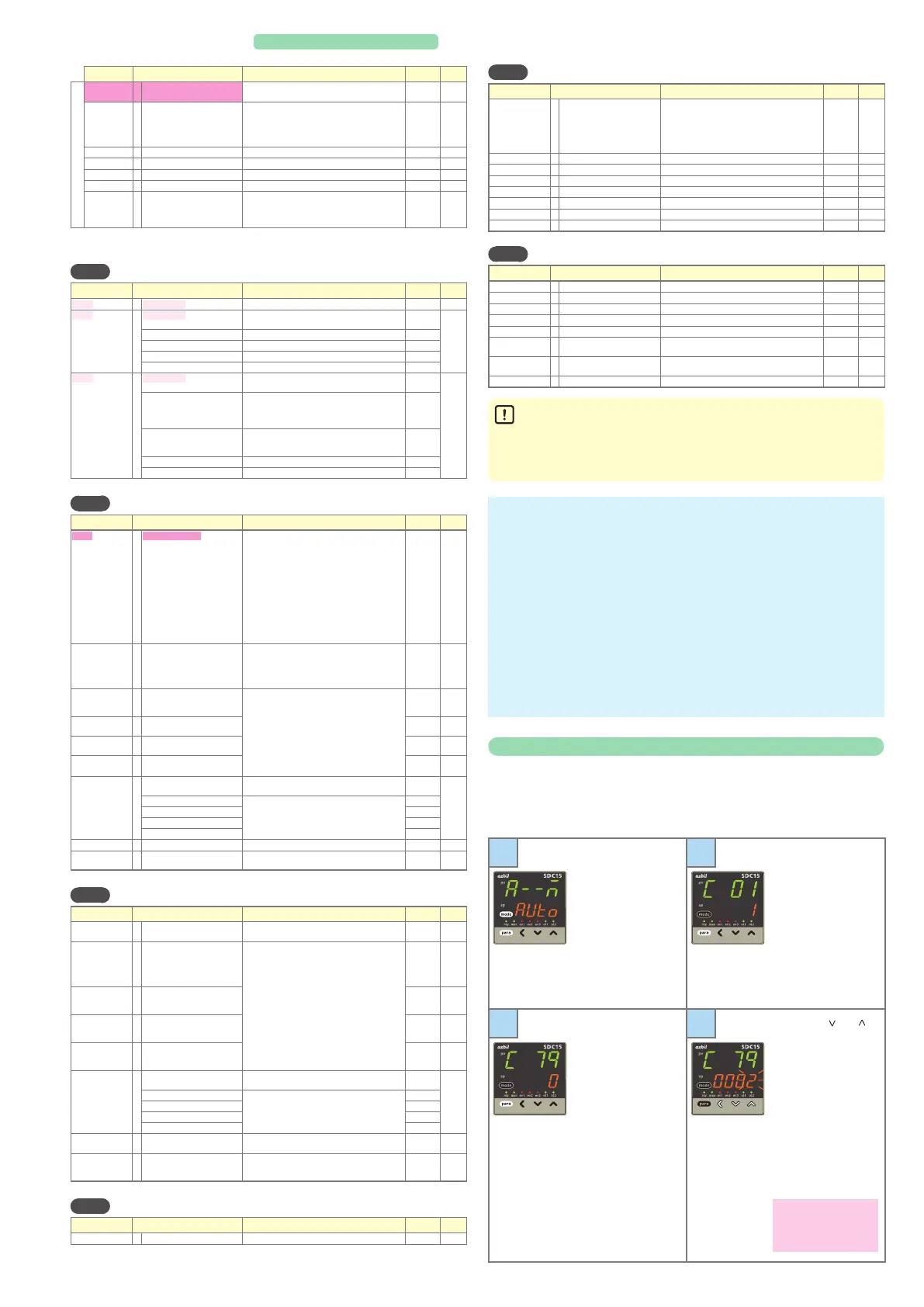
Memo
Changing the user level
This controller's user level can be set to 1 of 3 types in setup
C79
.
The number of possible displays and settings decreases according
to the user level: high function > standard > simple. All items are
displayed when high function is selected.
1
If necessary press
[mode] once to
change to the op-
eration display.
Next, press and hold
[para] for more than
2s to get the param-
eter setup display.
a--M
or
r--r
ap-
pears on the upper
display.
2
Press and hold
[para] for more than
2s again to display
c0
1
on the upper
display.
3
Press [para] repeat-
edly to change the
upper display to
c79
(user level).
4
When [<], [ ] or [ ]
is pressed, the lower
display flashes and
can be changed to
the desired numerical
value. Then, if no key
is pressed for more
than 2s, the displayed
value is set and the
display changes from
flashing to continu-
ously lit.
0: Simple configuration
(initial value)
1: Standard configuration
2:
High function configuration
• Items marked
in the tables are displayed in standard and/or high function configuration.
• To change a user level, refer to
Changing the user level
in the lower right part of this page.

 Loading...


