Design and Construction
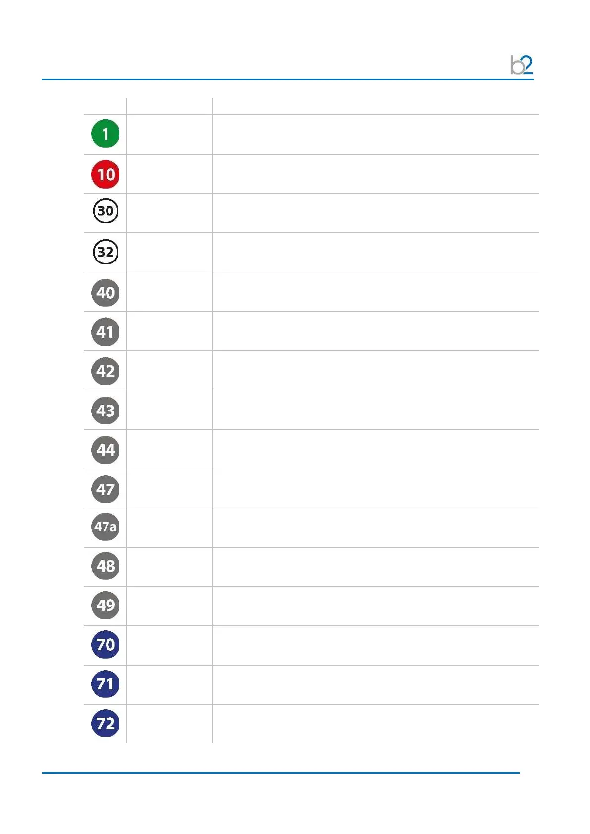
Earthing connector Serves as connection point from HVA to earth.
HV output
connector
Serves as connection point from the HVA to the HV test lead.
To connect Screw the HV test lead into the HV output connector and tighten
Power supply plug Serves as connection point from the HVA to the power source.
Communication
port
Serves as connection point from the HVA to PC (via RS232) or to a USB device
(via USB flash adapter).
HV switch [on/off]
Activates high voltage.
• To activate HV output Press within 10 seconds after START
Navigation knob
Enables user to select options and functions shown on display.
• To scroll selection up or down Rotate
• To enter selection Click (push in)
Emergency OFF
Activates emergency shutdown.
Operation is only possible when emergency OFF is released.
•
To activate emergency OFF
Key switch [on/off] Locks the unit to prevent against unauthorized use.
• To disable unit Remove key from the OFF Position
•
Replace key and turn to ON Position.
Main switch
[on/off]
Activates the HVA.
This switch is a fuse with integrated magnetic auto-reset 16 A
•
Turn the main switch OFF and then ON again
Remote control
interlock plug
Provides interlock for the remote switch (i.e. door interlock).
Can be connected to a remote emergency OFF switch, a gate, foot pedal or
dead man switch
External
HV
ON/OFF
Connection for an external HV ON/OFF button
Air vent Air inlet with filter, for cooling of electronic elements.
Air vent Air outlet, for cooling of electronic elements.
Display screen Displays menu, options and status information.
LED red Indicates HV status.
Red light indicates High voltage is ON (possible DANGER)
DUT not discharged residual voltage >100 V)
LED green Indicates HV status.
Green light indicates High voltage is OFF