WWW.BALTIMOREAIRCOIL.COM
5
Unit Weights
Before rigging any unit, the weight should be verified from the unit submittal drawing.
Anchoring
For the TSDC, 7/8” diameter holes are provided in the bottom flanges of the unit for
bolting the unit to the support beams. Refer to the suggested support drawing included
in the submittal for location and quantity of the mounting holes. The unit must be level
in both length and width directions for proper operation (max 1/16”/ft for the TSDC2 and
TSDF2). Anchor bolts must be provided by others, BAC recommends 3/4” bolt SAE J429
Grade 5, ASME A325 Type 1 or equivalent. If vibration isolated supports are to be used,
the units shall be installed on steel support first and the vibration isolators (provided
by others) should be mounted under the steel support. Refer to the vibration isolation
manufacturer’s guidelines before loading/unloading weight from the unit.
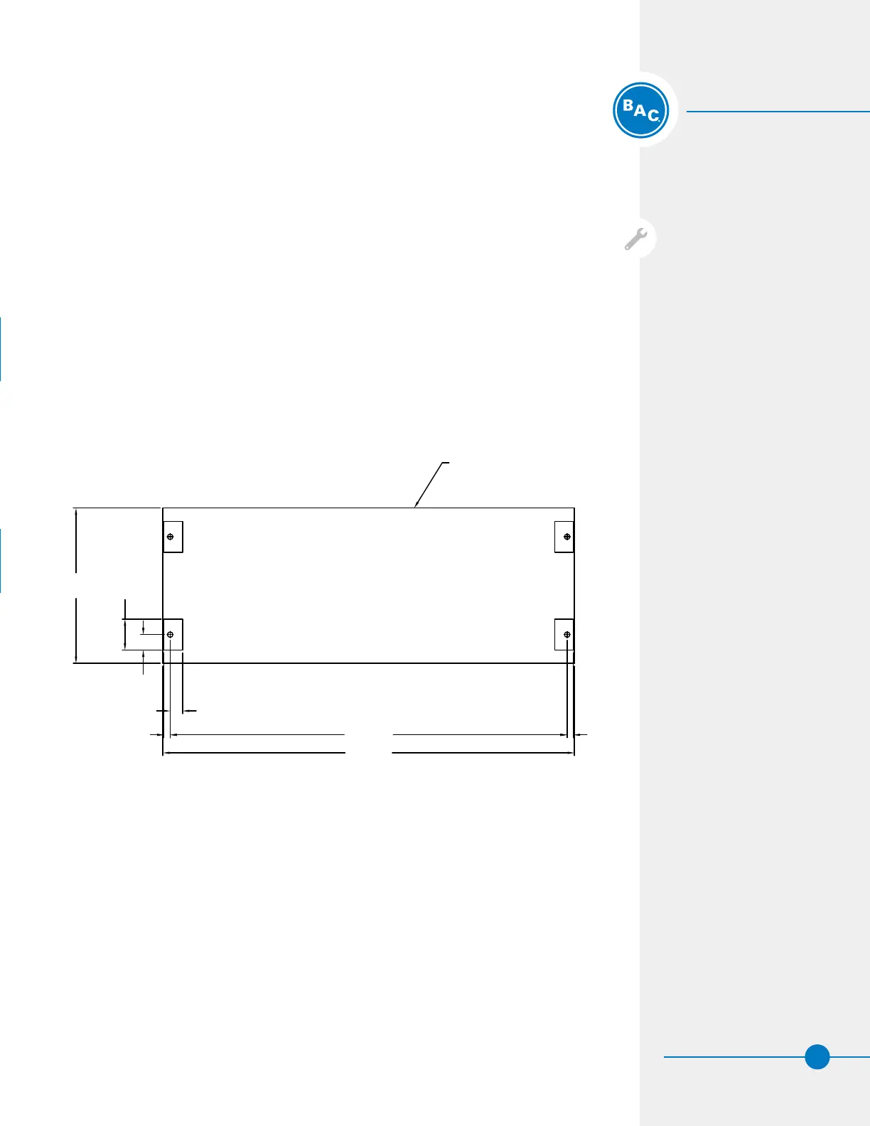
Point Support for Curb Mounting (For TSDC Only)
If mounting a TrilliumSeries™ Adiabatic Product on a curb, follow Figure 2 below for point
support locations.
NOTICE: Before an actual lift is
undertaken, open the access hatch
and check to ensure no water, snow,
ice, or debris has collected in the
sump or elsewhere in the unit. Such
accumulations will substantially
add to the equipment’s lifting
weight.
UNIT OUTLINE
AIR INLET
11'-0 1/2"
4'-2"
PLAN VIEW
AIR INLET
10'-7 7/8"
2" MIN
4" MIN
5"
10" MIN
CONNECTION END
POINT 1
POINT 2
POINT 3
POINT 4
2" MIN
Figure 2. Unit Point Support for Curb Installation (TSDC Only)
Rigging
Safety
Pre-Rigging Checks
Unit Weights
Anchoring
 Loading...