MGS Series Controller Manual
6709-9000 Rev 1 9
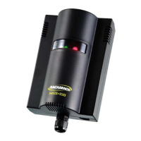
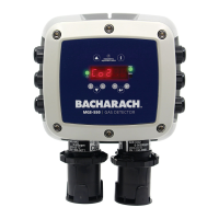
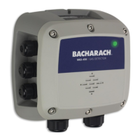
Components Descriptions
Power input Provides power to the MGS Controller
Power LED Power status indicator
Channels (max) 1-2 Channel Units 4-6 Channel Units
Sensor input(s) max 2 max 6 max
Alarm levels Single Dual Single Dual
Set point POT(s) 1 2 1 2
Alarm relay output(s) 1 2 1 2
Alarm LED(s) (max) 2 4 6 12
Fault relay output N/A N/A N/A 1
Figure 4. 6-Channel, Dual-Alarm MGS Controller
 Loading...