INTRODUCTION
WBPEEUI240756A0 A - 1
APPENDIX A - NTAI05 TERMINATION UNIT CONFIGURATION
INTRODUCTION
The IMFEC1
module can use the NTAI05 termination unit for
point-to-point operation. Select the input type of each channel
through the dipshunts on the termination unit. The FEC mod-
ule can accept inputs of 4 to 20 milliamps, 1 to 5 VDC, 0 to 1
VDC, 0 to 5 VDC, 0 to 10 VDC and -10 to +10 VDC.
NOTE:
Input jumpers J6 through J20 on the IMFEC11 board must
be set to the voltage position. Refer to
IMFEC11 Input Jumpers (J6
through J20)
in Section 3.
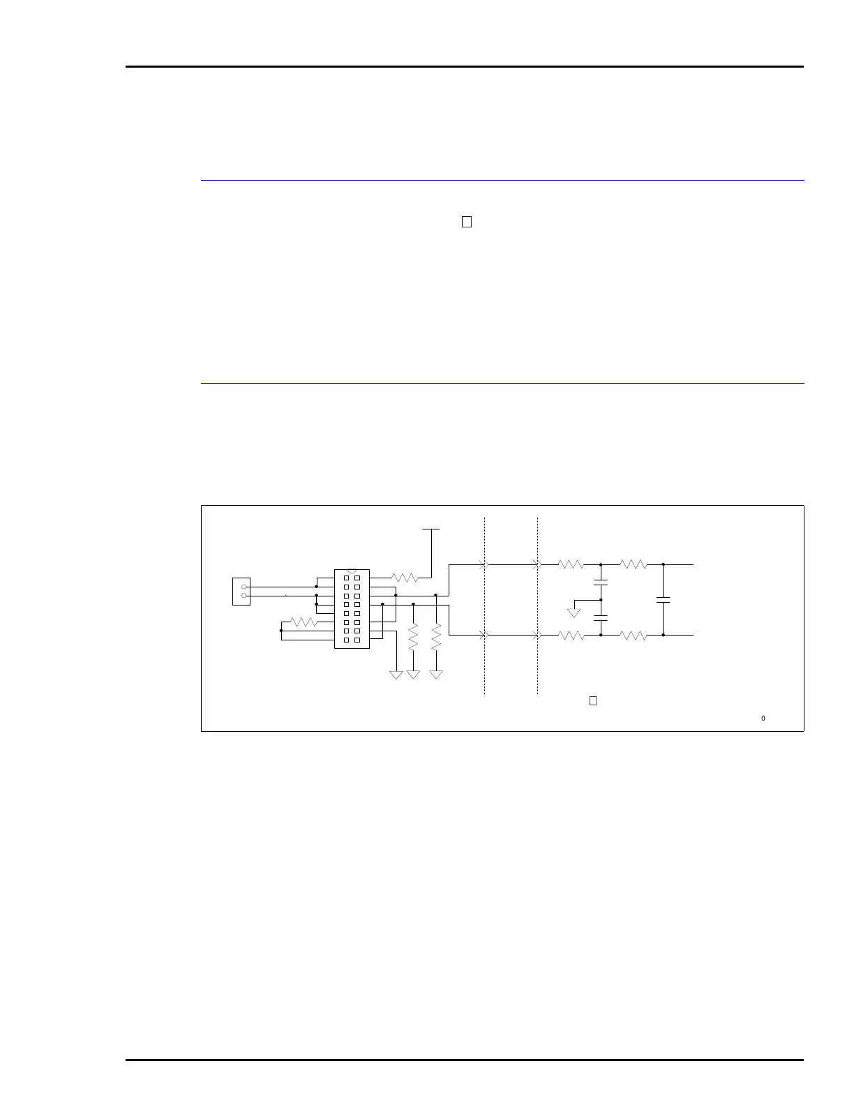
CONFIGURING INPUTS
Figure A-1 shows the input signal path through an NTAI05
dipshunt. Table A-1 shows NTAI05 dipshunt configurations.
Figure A-2 shows module to termination unit cabling and Fig-
ure A-3 shows the NTAI05 terminal assignments.
Figure A-1. NTAI05 Input Circuit
TERMINAL
BLOCK
DIPSHUNTS
XU1-XU16
+24 VDC
MULTIPLEX
CIRCUIT TO A/D
CONVERTER
TERMINATION UNIT
NTAI05
NKTU01 IMFEC1 INPUT CIRCUIT
T00921A
1 16
2 15
7 10
6 11
5 12
4 13
3 14
8 9
+
–