Dealer Development Center, Pune
70
Pulsar DTS-i 150/180 Training Notes
Dos & Don’ts
SWITCHES
• After washing the vehicle ensure to apply dry air on switches before
operation.
• Always ensure that grommets provided on clutch switch, front brake
switch and rear brake switch are intact.
• Always apply WD-40 Rust Spray to sticky switches.
• Do not apply direct pressurized water jet on control switches.
• Do not lubricate electrical switches by oil or grease.
• Do not over tighten the switches.
• During warranty period do not dismantle control switches.
• Do not add extra electrical loads e.g. musical horns, additional horns,
buzzers as it will reduce switch contact life & battery life &b a t t e r y
life.
• Do not operate switch immediately after water servicing.
Dos
3
Don'ts
7
Dealer Development Center, Pune
71
Pulsar DTS-i 150/180 Training Notes
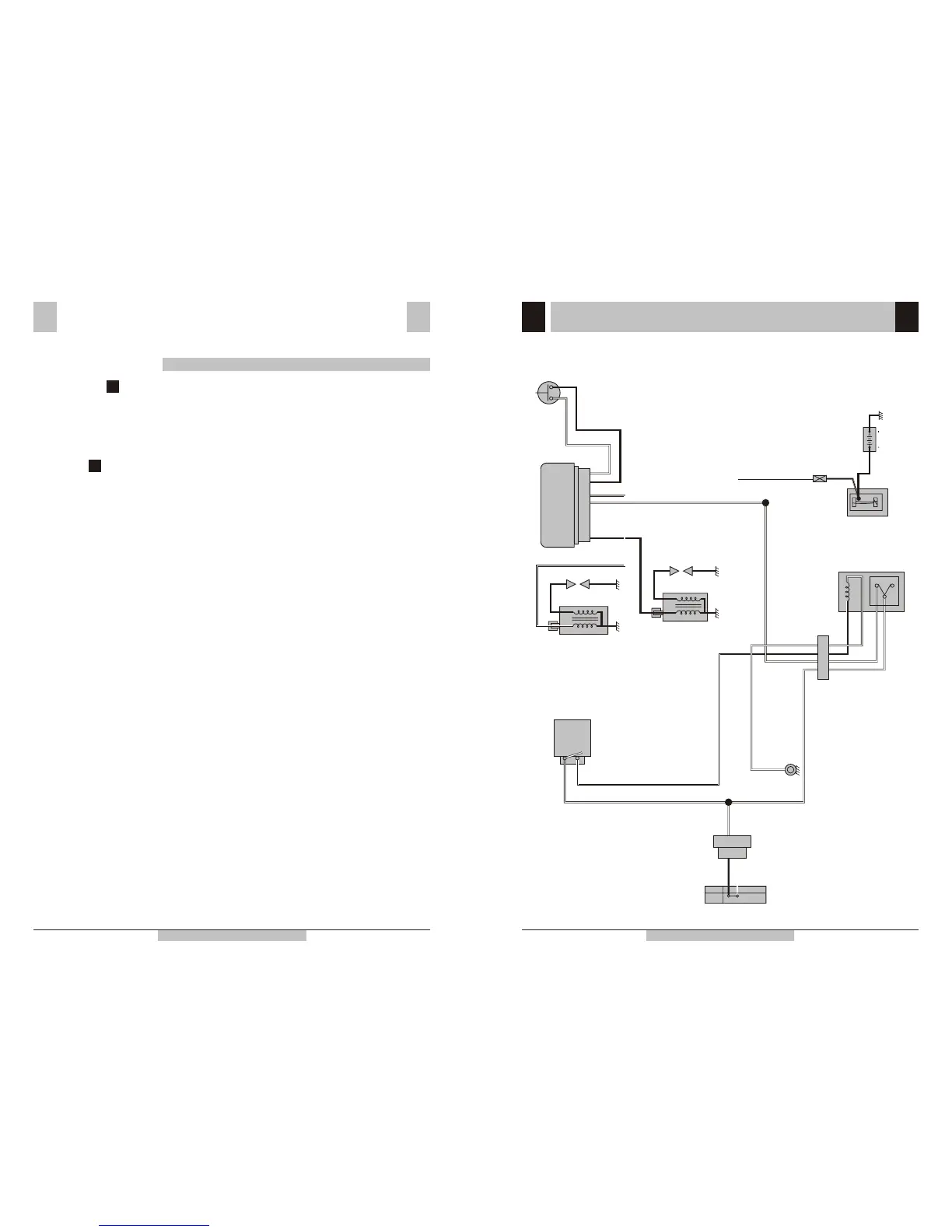
Electrical Circuit Diagrams
IGNITION CIRCUIT
W
SPARK PLUG
B
B
H.T.COIL
FUSE
(10 Amps.)
R
W/B
STARTER RELAY
100A RATING
BATTERY
12V-9Ah
O
F
F
O
N
B/Y
WW
Br
IGNITION SWITCH
EARTH-
FRAME
B/R
TPS
SWITCH
ASSY.
CONTROL
SWITCH RH
Br/R
B/R
Br/W
RELAY
(KILL SWITCH
CONTROL)
Br/L
B/Y
Pi
B/Y
Br/L
Br/L
W/G
Br/L
W/G
Br/W
NC
NO
P
SPARK PLUG
H.T.COIL
B/Y
W/G
B/Y
Br/W
B
DC C.D.I. ASSY.
Br/L
 Loading...