Document: 333D012G
5-18-2007
- 13 -
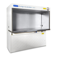
Cabinet
Model
Sash
Height
(Inches)
Exhaust Flow Range
(Approximate)
(CFM)
*Suction Min/Max
(Inches W.C.)
SG403A 8” [203.2mm] 322 / 520 [152 / 245 L/sec] 0.05 / 0.25 [12.4 / 62.3 Pa]
10” [254mm] 401 / 585 [189 / 276 L/sec] 0.08 / 0.30 [19.9 / 74.7 Pa]
SG603A 8” [203.2mm] 490 / 754 [231 / 356 L/sec] 0.15 / 0.40 [37.4 / 99.6 Pa]
10” [254mm] 613 / 914 [289 / 431 L/sec] 0.20 / 0.50 [49.8 / 124.5 Pa]
* NOTE: Water column suction is measured directly above the cabinet exhaust outlet before any dampers, elbows or other restrictions.
Exhaust Requirements for a CEC
IMPORTANT
NSF/ANSI 49 does not recommend using Hard Exhaust Connections (HEC) with
Class II, Type A2, Biosafety cabinets.
A Hard Exhaust Connection (HEC) requires a 10” [254mm] diameter connection between the cabinet and the
building exhaust duct with no air gaps. It mounts directly over the exhaust filter and includes an access panel for leak
checking the exhaust filter. We recommend having an airtight damper (ATD) to seal the cabinet for decontamination.
Cabinet
Model
Sash
Height
(Inches)
Exhaust Flow Range
(Approximate)
(CFM)
*Suction
(Inches W.C.)
SG403A 8” [203.2mm] 256 / 282 [121 / 133 L/sec] 0.06 [14.9 Pa]
10” [254mm] 318 / 352 [150 / 166 L/sec] 0.08 [19.9 Pa]
SG603A 8” [203.2mm] 388 / 428 [183 / 202 L/sec] 0.10 [24.9 Pa]
10” [254mm] 484 / 536 [228 / 253 L/sec] 0.15 [37.4 Pa]
* NOTE: Water column suction is measured directly above the cabinet exhaust outlet before any dampers, elbows or other restrictions.
Exhaust Requirements for a HEC