3.2. Mechanical
Connection
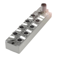
The BNI IOL modules are fastened with 3 M4 screws (position 1, Fig. 3-1/3-2).
3.3. Electrical
Connection
The BNI IOL-302-xxx-K006 modules do not require a separate supply voltage connection.
Supply voltage is provided via the IO-Link interface and the higher-level IO-Link master
module.
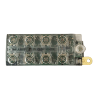
The modules are equipped with a ground connection.
Figure 3-3: BNI ground connection IOL-302...
➢ Connect the sensor hub module to the ground connection.
Note
The FE connection from the housing to the machine must have low-impedance
and be kept as short as possible.
The IO-Link connection is established via an M12 connector (A-coded, male).
IO-Link (M12, A-coded, male)
Supply voltage for controller US +24 V
Supply voltage for actuators UA, +24 V
C/Q, IO-Link data transmission channel