Balluff Network Interface / IO-Link BNI IOL-302-002-K006
www.balluff.com
Connecting the
sensor hub
➢ Connect ground conductor to the FE terminal, if available.
➢ Connect the incoming IO-Link cable to the sensor hub.
Note
A standardized sensor cable is used to connect to the higher-level IO-Link master
module. Maximum length of 20 m.
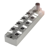
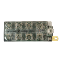
16 inputs/outputs, freely configurable
Digital input/output port (M12, A-coded, female)
Note
For the digital inputs, the input guideline specified in EN 61131-2, Type 3 applies.
Note
Unused input port sockets must be fitted with blind caps to ensure the IP67
protection rating.
Digital input/output port (M12, A-coded, female)
Extension port for actuator power supply
Note
A standardized sensor cable is used to connect to the device to be extended.
Maximum length of 20 m.