8 English
Menu functions for sensors with 2 switching points
First menu level
SP 1
FH 1
Menu 1 – Setting for switching point 1 Setting
for the relevant value from which switching
point 1 is activated.
If the window function in menu 5:6 is activated,
the value for switching point 1 represents the
upper pressure limit in the window (FH).
rP 1
FL 1
Menu 2 – Setting for return point 1 Setting for
the relevant value from which return point 1 is
activated.
If the window function in menu 5:6 is activated,
the return value for switching point 1
represents
the lower pressure limit in the window (FL).
SP 2
FH 2
Menu 3* – Setting for switching point 2 Setting
for the relevant value from which switching
point 2 is activated.
If the window function in menu 5:7 is activated,
the value for switching point 2 represents the
upper pressure limit in the window.
rP 2
FL 2
Menu 4* – Setting for return point 2 Setting for
the relevant value from which return point 2 is
activated.
If the window function in menu 5:7 is activated,
the return value for switching point 2 represents
the lower pressure limit in the window.
EF
Menu 5 – Extended functions
Second menu level
rES
Menu 5:1 – Reset
Restores all adjustable parameters to their
default settings and deletes the Min. and Max.
values
dS 1
Menu 5:2 – Switching delay time 1
Setting for the value of switching delay time 1,
which starts after switching point 1 is reached
(time range 0...50 seconds)
dr 1
Menu 5:3 – Return switching delay time 1
Setting for the value of return switching delay
time 1, which starts after return point 1 is
reached (time range 0...50 seconds)
dS 2
Menu 5:4
*
– Switching delay time 2
Setting for the value of switching delay time 2,
which starts after switching point 2 is reached
(time range 0...50 seconds)
dr 2
Menu 5:5
*
– Return switching delay time 2
Setting for the value of return switching delay
time 2, which starts after return point 2 is
reached (time range 0...50 seconds)
ou 1
Menu 5:6 – Output 1
Switching function of the switching output:
Hno = Hysteresis function, NO contact
Hnc = Hysteresis function, NC contact
Fno = Window function, NO contact
Fnc = Window function, NC contact
Menu functions (continued)
Second menu level (continued)
ou 2
Menu 5:7
*
– Output 2
Switching function of the switching output:
Hno = Hysteresis function, NO contact
Hnc = Hysteresis function, NC contact
Fno = Window function, NO contact
Fnc = Window function, NC contact
uni
Menu 5:8 Switching units
Selection of physical measuring unit for the
displayed and configured pressure value:
bAr = bar,
nnBa = mbar,
PSi = PSI,
mPA = MPa
FLiP
Menu 5:9 – Rotate display
Rotate the display 180°
Lo
Menu 5:10 - Min. value
Display of minimum pressure attained during
the measurement (the value is lost when the
power supply is interrupted)
Hi
Menu 5:11 - Max. value
Display of maximum pressure attained during
the measurement (the value is lost when the
power supply is interrupted)
---
Menu 5:12 – Deletion of Min and Max values
The display confirms that the process for
deleting the values has started
SET0
Menu 5:13 – Neutral point adjustments
Correction for the neutral point of the display
and of the analog output signal to up to
+/– 3% of the nominal pressure range
dAP
Menu 5:14 – Measure value damping
Configuration of the measure value damping
value (0...1000 ms in 10 ms increments)
codE
Menu 5:15 – Access protection
Setting the password for protecting access to
the menu
0000 = no password
0000...9999 adjustable
Legend
*
Menus marked with an asterisk
do not appear if the sensor has
an analog output.
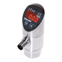
Pressure Sensors with IO-Link
BSP-B... /-V...
 Loading...
