20 english
6
Calibration procedure (continued)
6.5 Calibration procedure notes
Prerequisites
– The programming inputs are connected or the
calibration device is in place.
– The BTL is connected to the system controller.
– Voltage or current values from the BTL can be read
(using a multimeter, the system control or the adjusting
box).
Values for null and end point
– Any desired position of the magnet can be used as the
null or end point. However, the null and end points may
not be reversed.
– The absolute null and end points must lie within the
minimum or maximum range of what can be output
(see value table).
– The distance between the null point and end point
must be at least 4mm.
The last set values are always saved, regardless
of whether the setting was ended using the
buttons, the programming inputs or
automatically after 10min have expired.
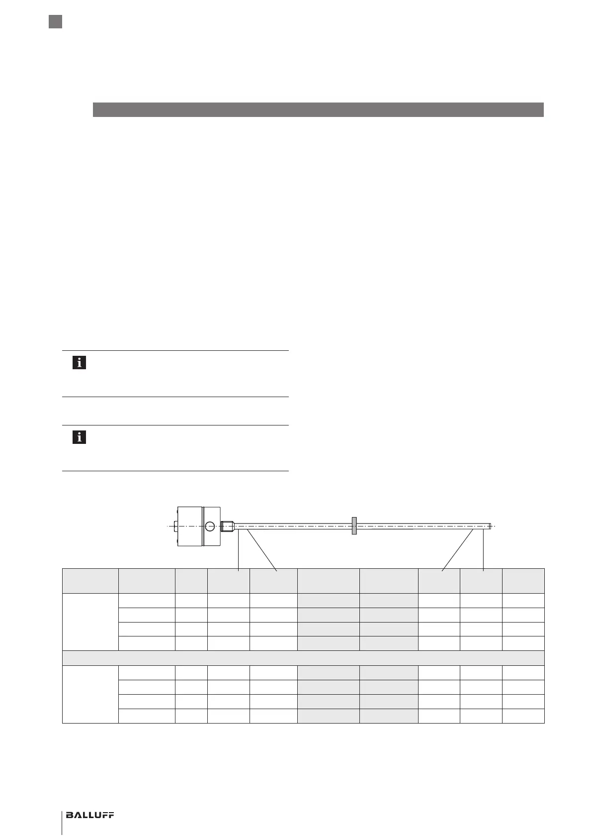
Value table for teach-in and inverting
The following examples refer to BTLs with 0 to
10 V or 4 to 20 mA output.
For all other versions, use the values in the value
table below.
Output
gradient
BTL Unit Min.
value
Nullvalue Indication for
adjustment
Indication
for teach-in
End
value
Max.
value
Error
value
Rising BTL7-A… V −0.5 0 2.0 4.0 +10.0 +10.5 +10.5
BTL7-G… V −10.5 −10.0 2.0 4.0 +10.0 +10.5 +10.5
BTL7-C… mA 0 0 6.0 12.0 20.0 20.4 20.4
BTL7-E… mA 3.6 4.0 6.0 12.0 20.0 20.4 3.6
Falling BTL7-A… V +10.5 +10.0 8.0 6.0 0 −0.5 −0.5
BTL7-G… V +10.5 +10.0 −2.0 −4.0 −10.0 −10.5 −10.5
BTL7-C… mA 20.4 20.0 14.0 8.0 0 0 20.4
BTL7-E… mA 20.4 20.0 14.0 8.0 4.0 3.6 3.6
Tab. 6-1: Value table for teach-in and inverting
Null point End point
BTL7-A/C/E/G5_ _-M_ _ _ _-J-DEXC-TA12
Magnetostrictive Linear Position Sensor – Rod Style
Type of protection “db” and “ta”
Flameproof enclosure
 Loading...