22 english
b
a
b
8
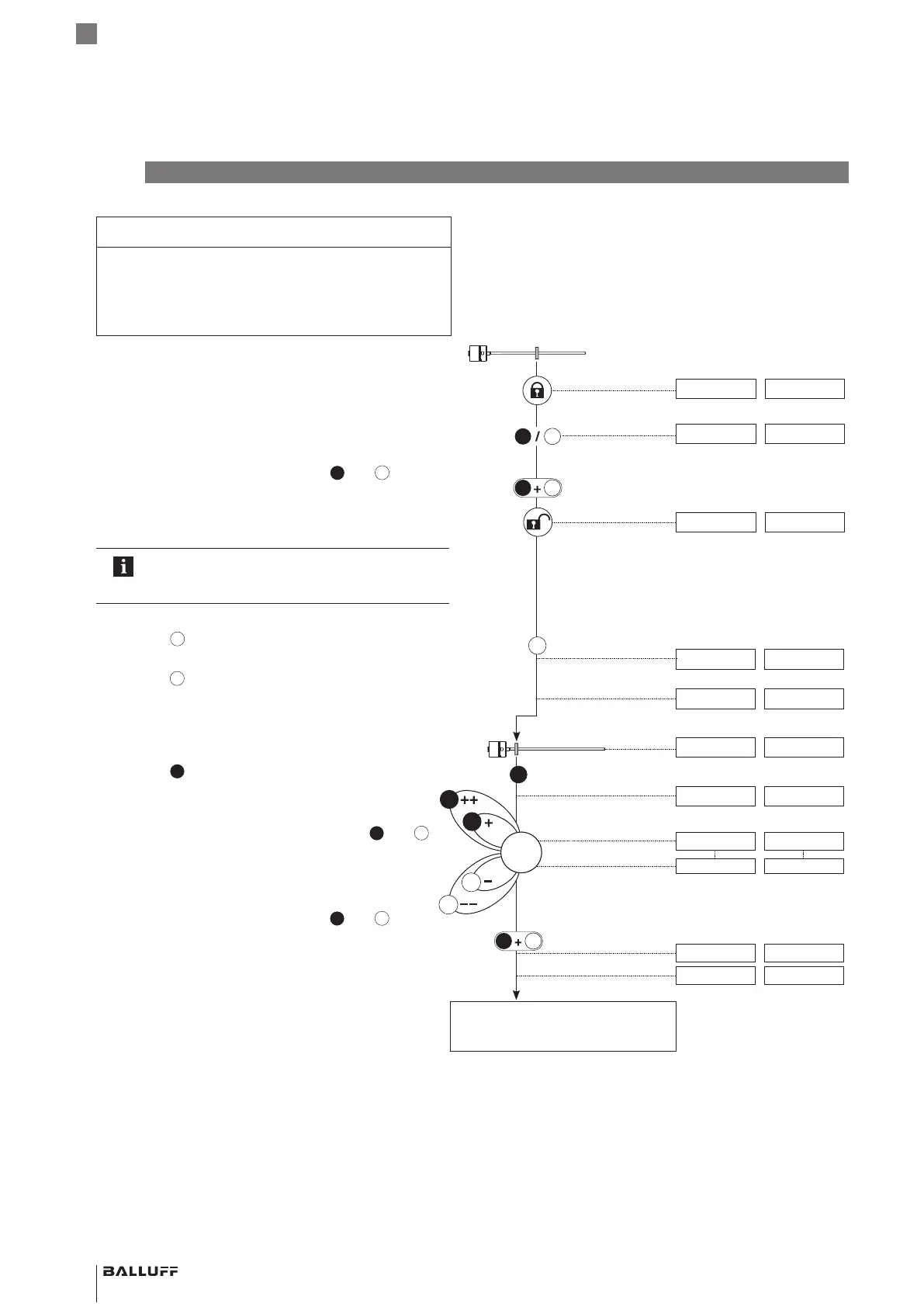
Adjusting
NOTICE
Interference in function
Adjustment while the system is running may result in
malfunctions.
► Stop the system before performing adjustment.
Displayed values (example)
At 0 to 10 V At 4 to 20 mA
Initial situation:
– BTL with magnet within measuring range
5.39 V 9.15 mA
1. Activate buttons
► Activate any button for at least 3s.
> 3 s
5.39 V 9.15 mA
► Release buttons.
< 1 s
► Simultaneously (within 1s) activate
and
for at
least 3s.
> 3 s
⇒ Output indicates error value.
10.50 V 3.60 mA
⇒ Buttons are activated.
If an error or an interruption occurs while
activating the buttons, allow a wait time of 12s
before retrying.
2. Select adjustment
► Activate
for at least 2s.
> 2s
⇒ Indication for “Adjustment” is displayed.
2.00 V 6.00mA
► Release
.
⇒ Current position value is displayed.
5.39 V 9.15 mA
3. Adjust start value
► Bring magnet to start position.
1.04 V 4.82 mA
► Activate
for at least 2s.
> 2s
⇒ Indication for “Adjust start value” is displayed.
0.00 V 4.00 mA
► Adjust start value.
⇒ The start value can be changed using
and
1)
.
The gradient of the output remains constant (see
page18).
1.04 V 4.82 mA
1.00 V 4.40 mA
► Exit calibration procedure: Activate
and
for no
more than 2 s.
< 2s
b
⇒ Indication for “Adjustment” is displayed.
2.00 V 6.00mA
⇒ Set position value is saved.
1.00 V 4.40 mA
Adjust end value
(see page23)
b
b
1) Briefly activate button: Current value is increased or
decreased by approx. 1mV or 1 µA.
If a button is activated longer than 1 s, the step interval is
increased.
BTL7-A/C/E/G5_ _-M_ _ _ _-J-DEXC-TA12
Magnetostrictive Linear Position Sensor – Rod Style
Type of protection “db” and “ta”
Flameproof enclosure
 Loading...