18 english
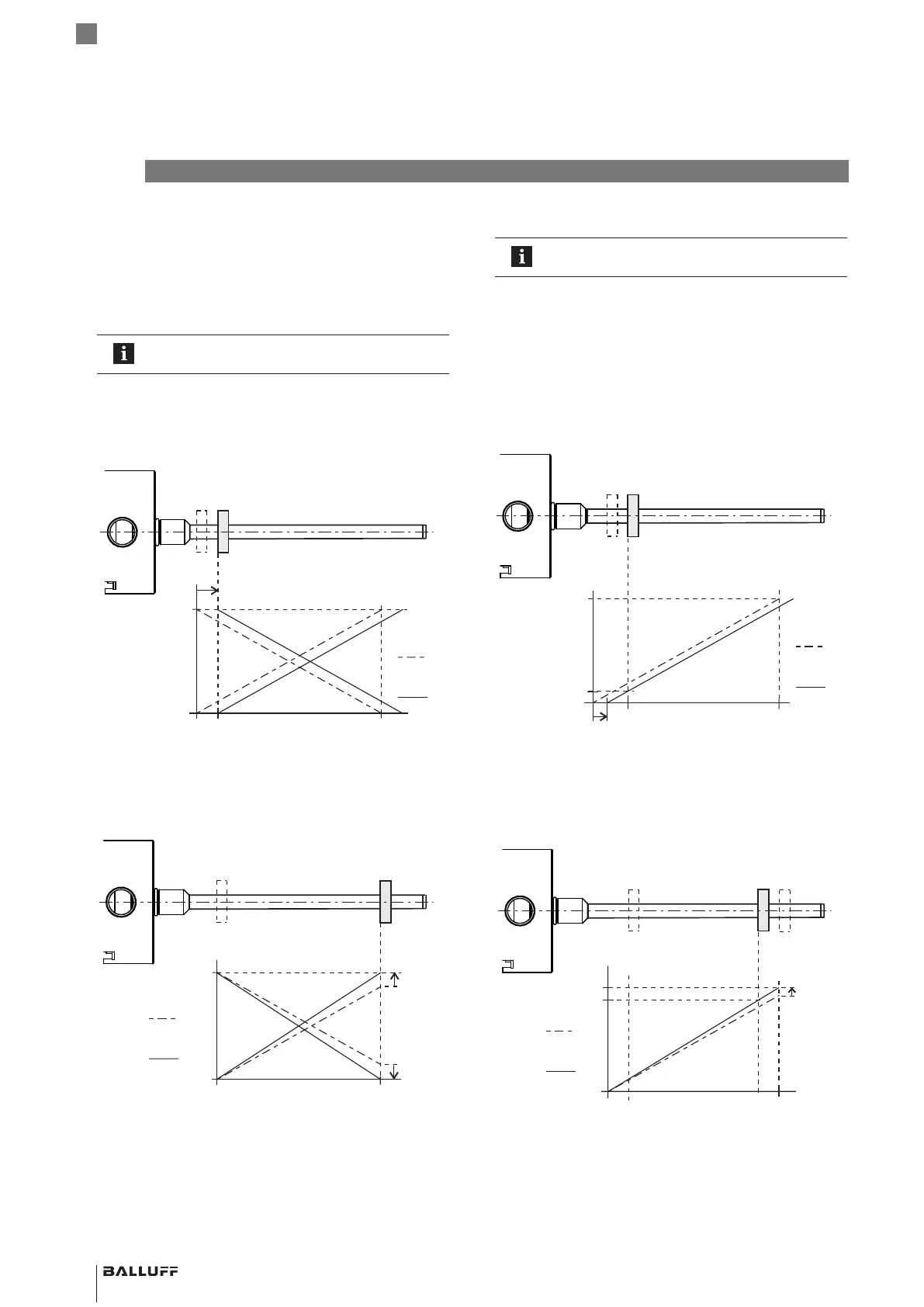
6.3.2 Adjusting
The detailed procedure for adjusting is
described on page22ff.
A new start and/or end value is adjusted. This is
recommended when the magnet cannot be brought to the
null point or end point.
Steps:
► Move magnet to the new start position.
► Set the desired start value by activating the buttons or
programming inputs.
Fig. 6-4:
New start value
Null point
Before
after
Adjusting new start position (offset shift)
► Move magnet to the new end position.
► Set the desired end value by activating the buttons or
programming inputs.
Fig. 6-5:
New end
value
Before
After
End point
Adjusting new end position (changing the output gradient)
6.3 Calibration procedure overview
6.3.1 Teach-in
The factory-set null point and end point are replaced by a
new null point and end point.
The detailed procedure for teach-in is described
on page21.
Steps:
► Move magnet to the new null position.
► Read new null point by activating the buttons or
programming inputs.
Fig. 6-2:
New null point
Before
After
Falling
Rising
Reading new null point (offset shift)
► Move magnet to the new end position.
► Read new end point by activating the buttons or
programming inputs.
Fig. 6-3:
New end point
Before
After
New measuring length 100%
Reading new end point (changing the output gradient)
6
Calibration procedure (continued)
BTL7-A/C/E/G5_ _-M_ _ _ _-J-DEXC-TA12
Magnetostrictive Linear Position Sensor – Rod Style
Type of protection “db” and “ta”
Flameproof enclosure