www.balluff.com 9english
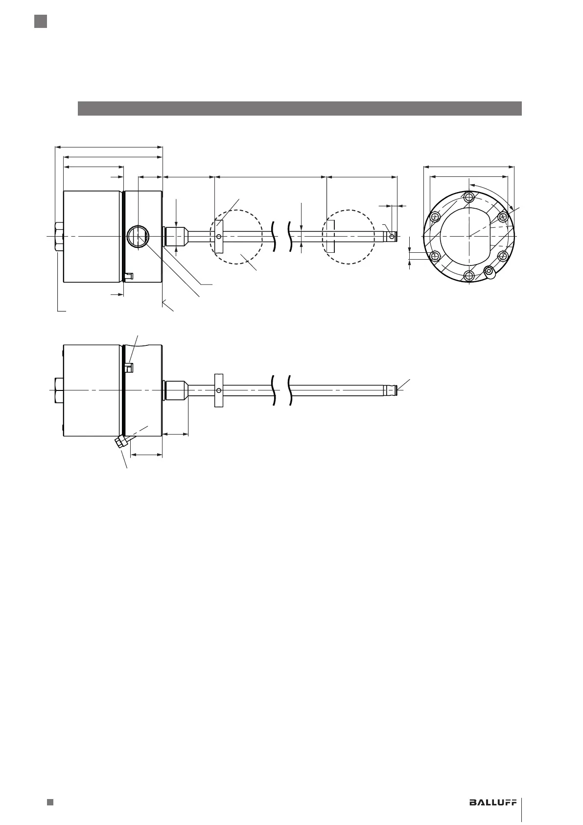
Fig. 3-1: BTL7-…, construction
3.1 Construction
Electrical connection: The connection is accomplished
by means of a connection terminal (see Type code on
page30).
Housing: A heavy-duty stainless steel housing with a
modified 1/2"-14 NPT threaded conduit opening for cable
entry (conduit is not included in the scope of delivery).
Modified conduit entry in accordance with FM Standard
3615, Chapter 3.3.3, Paragraph D, Section 1.
The internal electronics module can be replaced without
removing the pressure housing.
Fastening: For secure fastening, tighten the
BTL
with
cylinder screws (M6 × 45 - A4-70) at all 6 mounting holes
(see Fig. 3-1). All screws must be tightened with 3.5Nm.
The
BTLs
have an additional thread at the end of the rod
to support larger nominal lengths.
Magnet: Defines the position to be measured on the
waveguide. Magnets are available in various models and
must be ordered separately (see Accessories starting on
page28).
Nominal length: Defines the available measuring range.
Rods with various nominal stroke lengths from 25mm to
7620mm are available depending on the version.
Damping zone: Area at the end of the rod that cannot be
used for measurements, but which may be passed over.
3
Construction and function
50.8
104.1
A
30.8
23.6
96.1
59.5
77
Ø 10.2
Ø 18h6
A
25
Ø 4
5
6.7
Ø 88.5
Ø 76.2
6
0
°
Magnet
2)
Nominal length =
measuring range
Damping zone
1)
Mounting surface
A – A view
15/16" or 24mm key
Modified 1/2"-14 NPT (conduit entry)
O-ring
Thread
M4x6
1) Unusable area
2) Not included in scope of delivery
Float
2)
1)
Cover secondary retaining screw
External housing GND
BTL7-A/C/E/G5_ _-M_ _ _ _-J-DEXC-TA12
Magnetostrictive Linear Position Sensor – Rod Style
Type of protection “db” and “ta”
Flameproof enclosure