1.19 Appendix A. Specific Camera / Sensor Data 209
1.19.2.4.2.2 Snapshot mode
In snapshot mode, the image acquisition process consists off several sequential phases:
1.19.2.4.2.3 Trigger
Snapshot mode starts with a trigger. This can be either a hardware or a software signal.
The following trigger modes are available:
Mode Description
Continuous Free running, no external trigger signal needed.
OnLowLevel As long as trigger signal is Low camera acquires images with own timing.
OnHighLevel As long as trigger signal is High camera acquires images with own timing.
See also
Using external trigger with CMOS sensors (p. 160)
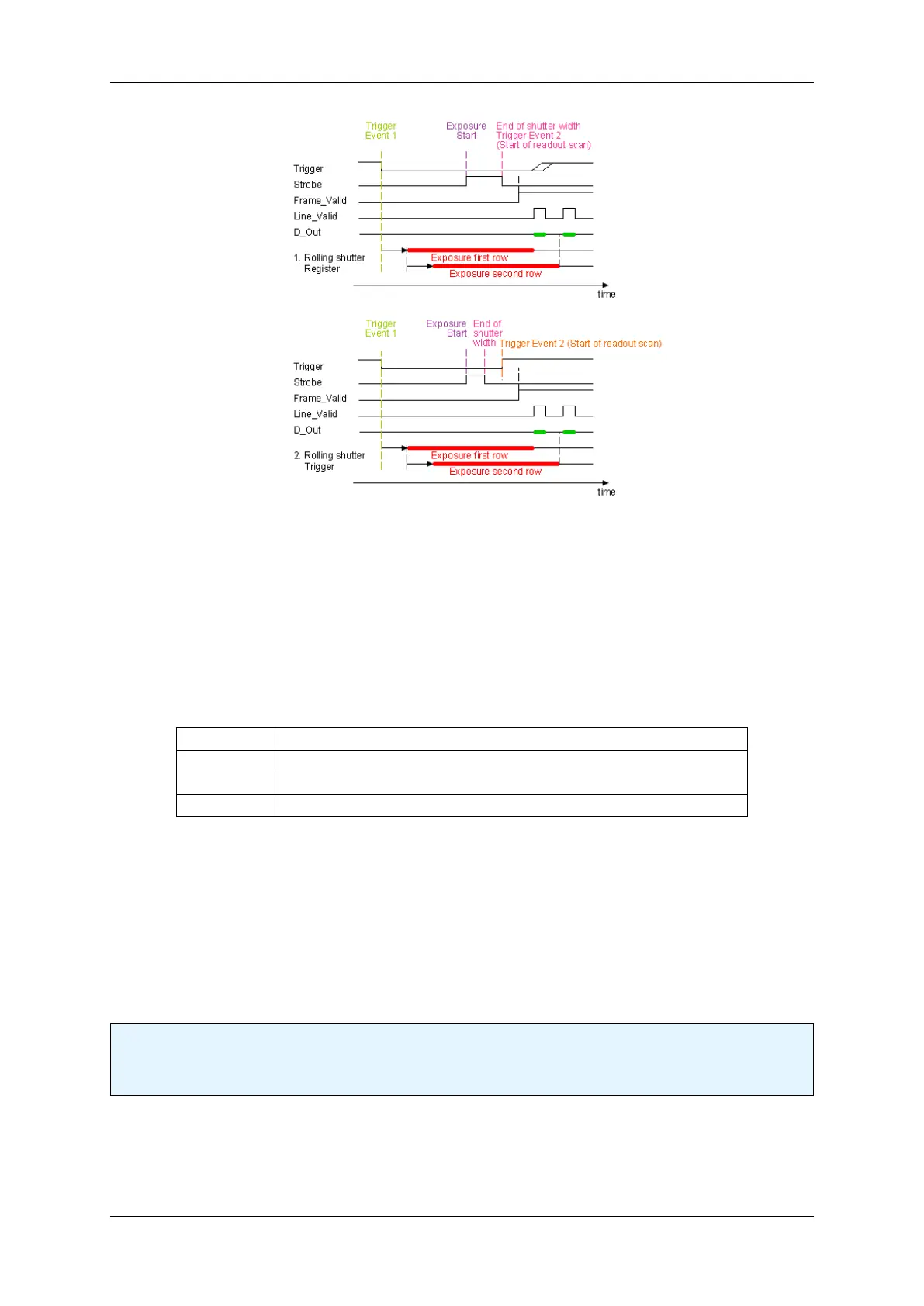
1.19.2.4.2.4 Erase, exposure and readout
All pixels are light sensitive at the same period of time. The whole pixel core is reset simultaneously and after the
exposure time all pixel values are sampled together on the storage node inside each pixel. The pixel core is read
out line-by-line after exposure.
Note
Exposure and read out cycle is carry-out in serial; that causes that no exposure is possible during read
out.
The step width for the exposure time is 1 us.
Image data is then shifted out line-by-line and transferred to memory.
To calculate the maximum frames per second (FPS
max
) in snapshot mode you will need following formula:
MATRIX VISION GmbH
 Loading...