1.9 Technical Data 45
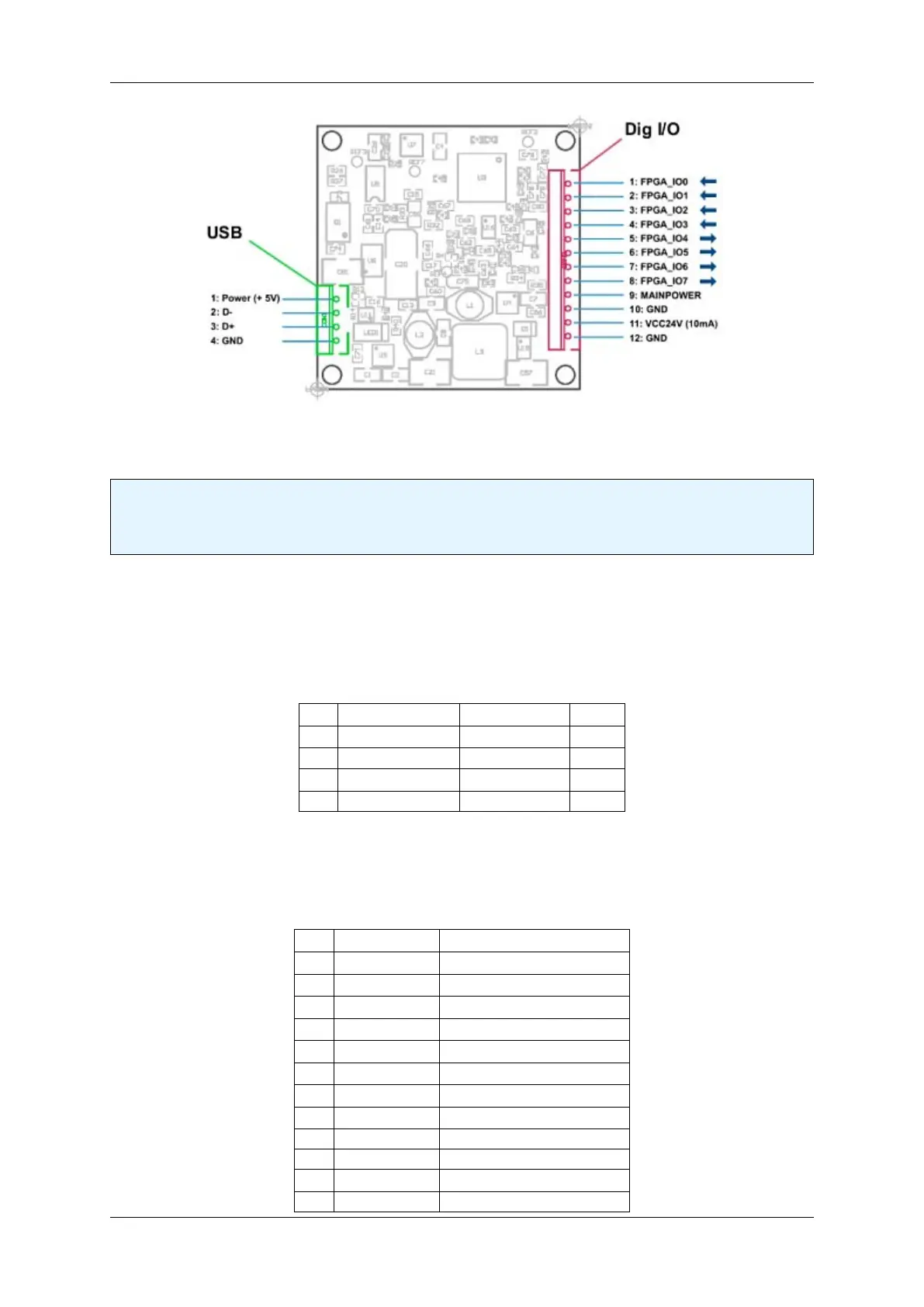
Figure 12: Backside view of the board
Note
The mvBlueFOX-M has a serial I²C bus EEPROM with 64 KBit of which 512 Bytes can be used to store
custom arbitrary data.
See also
UserDataEntry class description
Pin Signal Comment Cable
1 USBPOWER_IN Supply voltage red
2 USB_DATA- Data white
3 USB_DATA+ Data green
4 GND Ground black
1.9.3.1.1 4-pin Wire-to-Board header (USB 2.0) Manufacturer: JST
Part number: B4B-PH-K
Pin Signal Comment
1 FPGA_IO0 Digital In 0
2 FPGA_IO1 Digital In 1
3 FPGA_IO2 Digital In 2
4 FPGA_IO3 Digital In 3
5 FPGA_IO4 Digital Out 0
6 FPGA_IO5 Digital Out 1
7 FPGA_IO6 Digital Out 2
8 FPGA_IO7 Digital Out 3
9 MAINPOWER Current from the USB cable
10 GND Ground
11 VCC24V 24 V output (10mA)
12 GND Ground
MATRIX VISION GmbH
 Loading...