EasyManua.ls Logo

Baoli CPD30J - Page 105

Default Icon
124 pages
Print Icon
To Next Page IconTo Next Page
To Previous Page IconTo Previous Page
Loading...
100
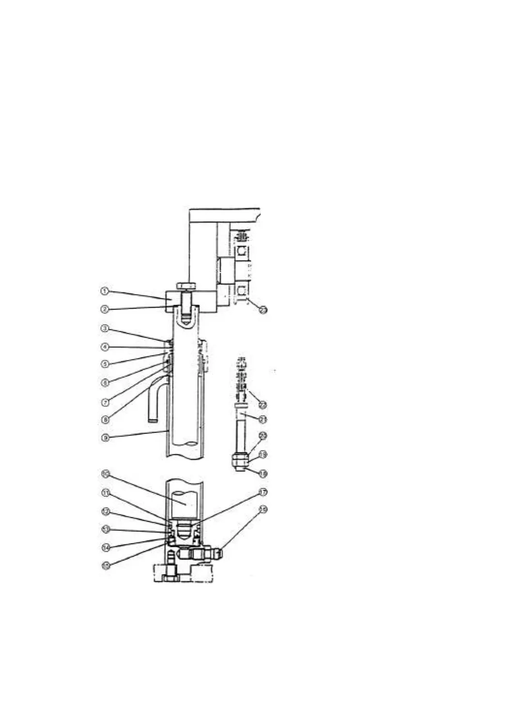
The piston, fastened to the piston rod with spring wire is fitted with oil seals and
wearing on its outer periphery.
At the bottom of the lift cylinder there is a cut-off valve, which operates when the
high-pressure hose bursts for any reason to prevent the load from dropping abruptly.
There are steel-backed bearing and oil seal assembled on cylinder head to support
the piston rod and prevent the dust. The diagram of lift cylinder is referred to Fig7-4.
Fig.7-4 Lift cylinder
1.
Upper beam
2.
Adjust shim
3.
Dust ring
4.
Oil seal
5.
Guide sleeve
6.
O-ring seal
7.
Cylinder head
8.
Steel-backed bearing
9.
Cylinder body
10.
Piston rod
11.
Piston
12.
Oil seal, piston
13.
Oil seal
14.
Ring
15.
Snap ring
16.
Cut-off valve
17.
Spring lock ring
18.
Cotter pin
19.
Nut, lock
20.
Nut, adjustment
21.
Joint
22.
Chain
23.
Chain wheel

Table of Contents