Table of Contents
Table of Contents..........................................iii
Introduction.......................................................1
About this document ......................................................................1
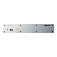
About the EXSTREAMER 1000 ................................................1
Hardware features.............................................................................1
Integrated Barix IP Audio Module.............................................1
Applications..........................................................................................1
Available Firmware............................................................................1
Hardware.............................................................2
Introduction.........................................................................................2
Functional block diagram...............................................................2
RS-232 Serial Interface....................................................................2
RS-485 Serial Interface....................................................................2
AES/EBU Interface.............................................................................2
Analog Audio Interface...................................................................2
IP Audio Module................................................................................2
USB Memory Interface....................................................................3
Network Interface.............................................................................3
Peripheral I/O Interface..................................................................3
LED I/O Status Display...................................................................3
Source Selection................................................................................3
Power supply........................................................................................3
Software reset button.....................................................................3
LED Status Display............................................................................3
Connectors..........................................................4
Connector placement......................................................................4
Front connector.................................................................................4
a) EXT. Connector...........................................................................4
Rear connectors.................................................................................4
A) Connector J1 Pin out...............................................................4
B) Connector J1 Pin out...............................................................4
C) Connector J2 Pin out..............................................................5
D) Connector J3 Pin out................................................................5
E) Connector J4 Pin out...............................................................5
F) Connector J5..................................................................................5
G) Connector J6 Pin out..............................................................6
H) Connector J7 Pin out..............................................................6
Table of Contents ii