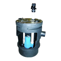
Stainless Rail Package (Not Shown)- The package system
comes complete and ready to place into the ground as outlined
in the project specifications. The moveable portion of the Break
Away Fitting (BAF), check valve, piping and guide bracket
comes assembled on the pump along with the lifting cable.
Insert pump bracket and moveable portion of BAF into the guide
channel and lower pump into basin (DO NOT DROP). Now
connect power and control cables to the junction box or control
panel depending on system design.
C-3) Liquid Level Controls:
The level controls are to be supported by a mounting bracket
that is attached to the sump wall, cover or junction box. Cord
grips are used to hold the cords in place on the mounting
bracket. The control level can be changed by loosening the grip
and adjusting the cord length as per the plans and
specifications. Be certain that the level controls cannot hang up
or foul in it’s swing and that the pump is completely submerged
when the level control is in the "Off" mode.
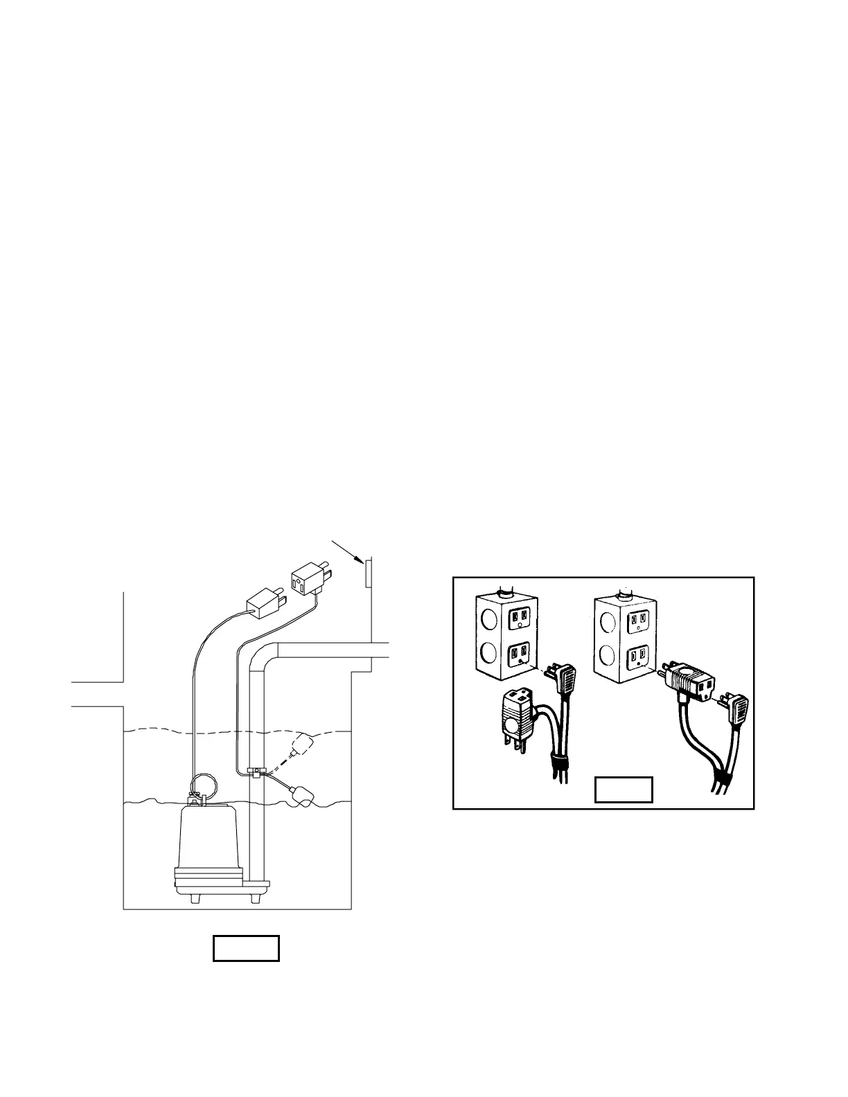
Figure 2 shows a typical installation for any submersible pump
using a level control with a piggy-back plug.
General Comments:
1) Never work in the sump with the power on.
2) Level controls are factory set for a pumping differential of 9
inches. If that is the cycle desired, simply circle the discharge
pipe with the pipe mounting strap, feed the end through the
worm drive, and tighten with a screwdriver. Be certain that the
level control cannot hang up or foul in it’s swing. Also, make
certain the pump impeller is still submerged when the level
control is in the ’off’ mode.
3) If a higher pump differential is needed, grip the cord near the
neck of the float, then using the other hand, exert a steady force
on the lower edge of the cable clamp. The cable clamp should
slide up to the new pivot point. Attach the level control to the
discharge hose in the manner described above.
4) Plug the level control plug into the receptacle, then plug the
pump into the piggyback plug. One cycle of operation should
be observed, so that any potential problems can be corrected.
5) It is recommended that the float should be set to insure that
the sump well liquid level never drops below the top of the motor
housing.
6.) Figure 3 shows a typical connection for pumps with the wide
angle float and piggy-back plug. For manual and automatic
operations.
Automatic - Plug float cord into outlet, then plug
pump cord into float cord.
Manual - Plug pump cord directly into outlet.
WALL
SOCKET
DISCHARGE Î
Î INFLOW
TYPICAL INSTALLATION WITH
WIDE ANGLE LEVEL CONTROL
ON
OFF
Fig. 2
Fig. 3
Automatic
Manual
7
 Loading...