C-4) Electrical Connections:
An acceptable motor control switch shall be provided at the
time of installation.
WARNING!
ALL MODEL PUMPS AND CONTROL PANELS MUST
BE PROPERLY GROUNDED PER THE NATIONAL
ELECTRIC CODE OR CANADIAN ELECTRIC CODE,
STATE, PROVINCE AND LOCAL CODES.
IMPROPER GROUNDING VOIDS WARRANTY.
C-4.1) Power Cable:
The cord assembly mounted to the pump must not be
modified in any way except for shortening to a specific
application. Any splice between the pump and the control
panel must be made in accordance with all applicable electric
codes. It is recommended that a junction box, if used, be
mounted outside the sump or be of at least Nema 4
(EEMAC-4) construction if located within the wet well. Do not
use the power cable to lift pump. NOTE: The white wire is
NOT a neutral or ground lead, but a power carrying
conductor.
C-4.2) Control Cable:
The cord assembly mounted to the pump must not be
modified in any way except for shortening to a specific
application. Any splice between the pump and the control
panel must be made in accordance with all applicable electric
codes. It is recommended that a junction box, if used, be
mounted outside the sump or be of at least Nema 4
(EEMAC-4) construction if located within the wet well. Do not
use the control cable to lift pump. NOTE: The white wire
is NOT a neutral or ground lead, but a power carrying
conductor.
C-4.3) Overload Protection :
C-4.3-1) Three Phase (Optional) - The normally closed
(N/C) thermal sensor is embedded in the motor windings
and will detect excessive heat in the event an overload
condition occurs. The thermal sensor will trip when the
windings become too hot and will automatically reset itself
when the pump motor cools to a save temperature. It is
recommended that the thermal sensor be connected in series
to an alarm device to alert the operator of an overload
condition, and/or the motor starter coil to stop the pump. In
the event of an overload, the source of this condition should
be determined and rectified immediately. DO NOT LET THE
PUMP CYCLE OR RUN IF AN OVERLOAD CONDITION
OCCURS !
C-4.3-2) Single Phase (Standard) - The type of in-winding
overload protector used is referred to as an inherent
overheating protector and operates on the combined effect
of temperature and current. This means that the overload
protector will trip out and shut the pump off if the windings
become too hot, or the load current passing through them
becomes too high. It will then automatically reset and start
the pump up after the motor cools to a safe temperature. In
the event of an overload, the source of this condition should
be determined and rectified immediately. DO NOT LET THE
PUMP CYCLE OR RUN IF AN OVERLOAD CONDITION
OCCURS !
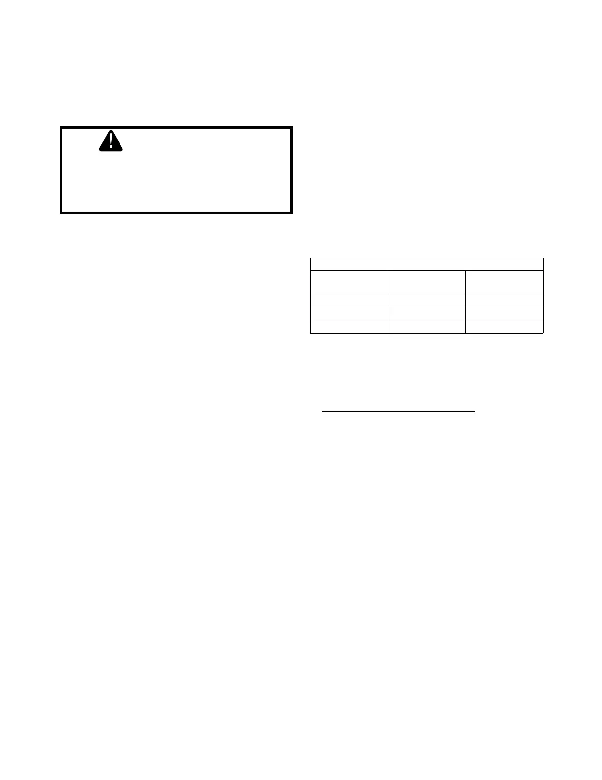
If current through the temperature sensor exceeds the values
listed, an intermediate control circuit relay must be used to
reduce the current or the sensor will not work properly.
TEMPERATURE SENSOR ELECTRICAL RATINGS
Volts Continuous
Amperes
Inrush
Amperes
110-120 3.00 30.0
220-240 1.50 15.0
440-480 0.75 7.5
C-4.4) Wire Size:
Consult a qualified electrician for proper wire size if additional
power cable length is required. See table for electrical
information.
SECTION: D START-UP OPERATION
D-1) Check Voltage and Phase:
Before operating pump, compare the voltage and phase
information stamped on the pump identification plate to the
available power.
D-2) Check Pump Rotation:
Before putting pump into service for the first time, the motor
rotation must be checked. Improper motor rotation can result
in poor pump performance and can damage the motor and/or
pump. To check the rotation, suspend the pump freely,
momentarily apply power and observe the "kickback".
"Kickback" should always be in a counter-clockwise direction
as viewed from the top of the pump motor housing.
D-2.1) Incorrect Rotation for Three-Phase Pumps:
In the event that the rotation is incorrect for a three-phase
installation, interchange any two power cable leads at the
control box. DO NOT change leads in the cable housing in the
motor. Recheck the "kickback" rotation again by momentarily
applying power.
D-2.2) Incorrect Rotation for Single-Phase Pumps:
In the unlikely event that the rotation is incorrect for a single
phase pump, contact a Barnes Pumps Service Center.
8
 Loading...