Operation Manual no. BP/IO/21/16 ed. 5.2.1
On a safety device side there is an information plate with permissible parameters of spark-
proof circuits and a simplified diagram facilitating the connection.
8 Construction and principle of operation
8.1 Mechanical structure
16
21 22
19 20
18
23
24
17
1 2
3
7
8
9
PolskaSp.zo.o.
ER100ims
RESET
AUTO
RESET
ON
OFF
ERR
OK
R
[k ]Ω
AN
Delay
[sec]
2
20
40
60
120
80
0
0,8
1,6
?
?
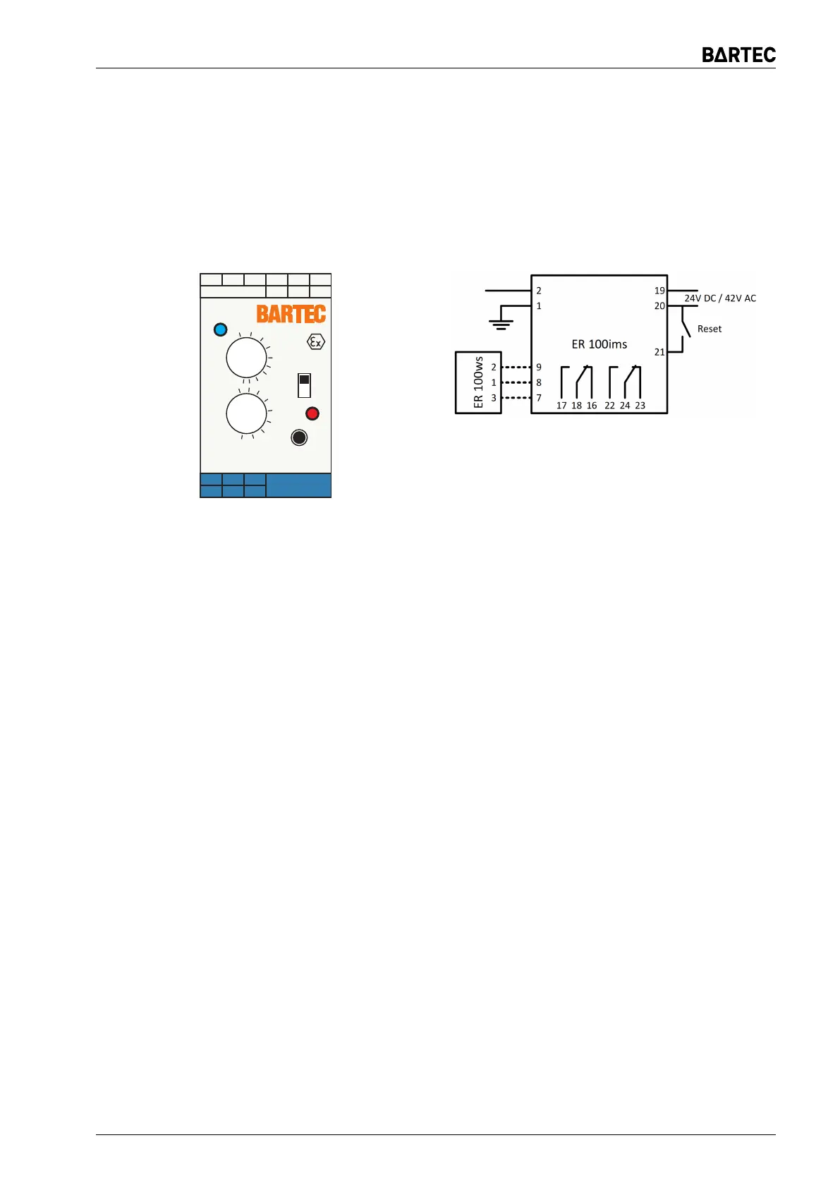
(a) Front of the device
(b) Terminal layout
Figure 1: Protection ER 100ims
All electronic components are placed on two printed circuits in an ME 35 UT enclosure moun-
ted on a TS35 bus. Terminals (terminals 1, 2, 3, 7, 8, 9) of spark-proof circuits are located on
one side of the enclosure, while the power supply (terminals 19, 20) and non-spark-proof outputs
(terminals 16, 17, 18, 22, 23, 24), resetting the response state (terminals 20, 21) are located on
the opposite side. Such arrangement ensures proper separation between the spark-proof and
non-spark-proof sides.
The measuring circuit consists of one to three ED100i chokes waterproofed by a fill in a plastic
enclosure, bolted to the circuit board or it is made by direct connection to the neutral point of the
transformer. The relay and appropriate connection of measuring chokes make one inseparable
whole.
8.2 Electrical equipment
8.2.1 Scheme of connections
The ER 100ims safety device is connected to the power supply through terminals 19, 20 of
the connection port. An integrated pulse power supply with a separating transformer and a spark-
proof barrier feeds a spark-safe voltage to electronic components and to the measuring circuit,
which through terminals 1 and 2 is connected to the controlled network. The output relay is
activated at properly operating network and drops out in the event of disturbance. It has two
contacts with terminals 16, 17, 18 and 22, 23, 24. A spark-proof analogue measuring output is
allocated to terminals (3) 9, 8. A spark-proof measuring instrument may be connected to the
aforementioned terminals, e.g. resistance indicator ER 100ws or spark-proof signal separator to
work with another control or transmission system. As standard, terminals 3 and 9 are internally
connected. For „/J” variant, terminals 3 and 9 should be connected from the outside of the unit. It
ER 100ims Page 11